Inst ToolsInst ToolsInst Tools
  • Courses
  • Automation
    • PLC
    • Control System
    • Safety System
    • Communication
    • Fire & Gas System
  • Instrumentation
    • Design
    • Pressure
    • Temperature
    • Flow
    • Level
    • Vibration
    • Analyzer
    • Control Valve
    • Switch
    • Calibration
    • Erection & Commissioning
  • Interview
    • Instrumentation
    • Electrical
    • Electronics
    • Practical
  • Q&A
    • Instrumentation
    • Control System
    • Electrical
    • Electronics
    • Analog Electronics
    • Digital Electronics
    • Power Electronics
    • Microprocessor
  • Request
Search
  • Books
  • Software
  • Projects
  • Process
  • Tools
  • Basics
  • Formula
  • Power Plant
  • Root Cause Analysis
  • Electrical Basics
  • Animation
  • Standards
  • 4-20 mA Course
  • Siemens PLC Course
Reading: Piping and Instrumentation Drawing (P&ID) Tutorials – Part 4
Share
Notification Show More
Font ResizerAa
Inst ToolsInst Tools
Font ResizerAa
  • Courses
  • Design
  • PLC
  • Interview
  • Control System
Search
  • Courses
  • Automation
    • PLC
    • Control System
    • Safety System
    • Communication
    • Fire & Gas System
  • Instrumentation
    • Design
    • Pressure
    • Temperature
    • Flow
    • Level
    • Vibration
    • Analyzer
    • Control Valve
    • Switch
    • Calibration
    • Erection & Commissioning
  • Interview
    • Instrumentation
    • Electrical
    • Electronics
    • Practical
  • Q&A
    • Instrumentation
    • Control System
    • Electrical
    • Electronics
    • Analog Electronics
    • Digital Electronics
    • Power Electronics
    • Microprocessor
  • Request
Follow US
All rights reserved. Reproduction in whole or in part without written permission is prohibited.
Inst Tools > Blog > Common > Piping and Instrumentation Drawing (P&ID) Tutorials – Part 4

Piping and Instrumentation Drawing (P&ID) Tutorials – Part 4

Last updated: January 21, 2020 12:13 pm
Editorial Staff
Common
No Comments
Share
4 Min Read
SHARE

Reading Engineering P&IDs

Standards and conventions have been developed to provide consistency from drawing to drawing. To accurately interpret a drawing, these standards and conventions must be understood.

Standards and Conventions for Valve Status

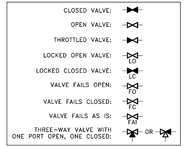
Before a diagram or print can be properly read and understood, the basic conventions used by P&IDs to denote valve positions and failure modes must be understood. The reader must be able to determine the valve position, know if this position is normal, know how the valve will fail, and in some cases know if the valve is normally locked in that position.

Figure 17 illustrates the symbols used to indicate valve status. Unless otherwise stated, P&IDs indicate valves in their “normal” position. This is usually interpreted as the normal or primary flowpath for the system. An exception is safety systems, which are normally shown in their standby or non-accident condition.

P & ID Valve Status Symbols

Figure 17 : Valve Status Symbols

3-way valves are sometimes drawn in the position that they will fail to instead of always being drawn in their “normal” position. This will either be defined as the standard by the system of drawings or noted in some manner on the individual drawings.

P&ID Document Reading Example

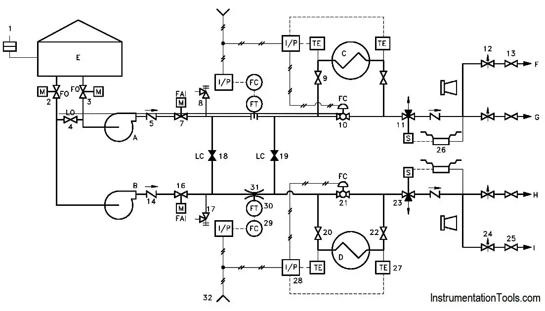
Example : At this point, all the symbols for valves and major components have been presented, as have the conventions for identifying the condition of a system.

Refer to Figure 18 as necessary to answer the following questions. The answers are provided in the back of this section so that you may judge your own knowledge level.

Example P&ID

Figure 18 : Exercise P&ID

1. Identify the following components by letter or number.

  • a. Centrifugal pump
  • b. Heat exchanger
  • c. Tank
  • d. Venturi
  • e. Rupture disc
  • f. Relief valve
  • g. Motor-operated valve
  • h. Air-operated valve
  • i. Throttle valve
  • j. Conductivity cell
  • k. Air line
  • l. Current-to-pneumatic converter
  • m. Check valve
  • n. A locked-closed valve
  • o. A closed valve
  • p. A locked-open valve
  • q. A solenoid valve

2. What is the controlling parameter for Valves 10 and 21?

3. Which valves would need to change position in order for Pump B to supply flow to only points G and H?

4. Which valves will fail open? Fail closed? Fail as is?

Answers :

1.

  • a. A or B
  • b. C or D
  • c. E
  • d. 31
  • e. 1
  • f. 8 or 17
  • g. 2,3,7 or 16
  • h. 10, 21
  • i. 12 or 24
  • j. 26
  • k. 32
  • l. 28
  • m. 5 or 14
  • n. 18 or 19
  • o. 18 or 19
  • p. 4
  • q. 11 or 23

2. Temperature as sensed by the temperature elements (TE)

3.

  • Open 18 and/or 19,
  • Shut 13 and 25

4.

  • Fail Open: 2 and 3
  • Fail Closed: 10 and 21
  • Fail as is: 7 and 16
Don't Miss Our Updates
Be the first to get exclusive content straight to your email.
We promise not to spam you. You can unsubscribe at any time.
Invalid email address
You've successfully subscribed !

Continue Reading

Difference Between Emergency STOP and Emergency Power OFF
What is Linear Motion Control? – Factors and Example Devices
The Role of CNC Machining in Electronics Manufacturing
Modern Instrumentation & IoT: Key Innovations & Trends
Applications of Robots in Various Fields
Cable Shielding – Purpose, Selection, Grounding
Share This Article
Facebook Whatsapp Whatsapp LinkedIn Copy Link
Share
Leave a Comment

Leave a Reply Cancel reply

Your email address will not be published. Required fields are marked *

Stay Connected

128.3kFollowersLike
69.1kFollowersFollow
210kSubscribersSubscribe
38kFollowersFollow

Categories

Explore More

Classification of Weighing Balance and Weight
Look Listen Feel of Instruments – Instrumentation Engineer Maintenance
Fiber Optic Cable vs Coaxial Cable
Load Cell Working Principle
Benefits of IoT in the Manufacturing Industry
What is a Router? How Does a Router Work?
5 Ways CNC Machining is Benefiting the Glass Industry
Why PDMS is Used For Fabrication?

Keep Learning

Best Engineering Mobile Apps

Best Engineering Mobile Apps on Google Play & App Store

Classification of HVAC chillers

Classification of HVAC Chillers

Sensors Used in Automotive Vehicles

Different Types of Sensors used in Automotive Vehicles

Isometric Projection

Piping and Instrumentation Drawing (P&ID) Tutorials – Part 2

Plant Engineering Drawings

Piping and Instrumentation Drawing (P&ID) Tutorials – Part 1

Static and Dynamic Characteristics of an Instrument

Static and Dynamic Characteristics of an Instrument

Solar Arrays

Solar Photovoltaic Cells – Parts of the Solar Panel

Basic Pneumatic System

Introduction to Fluid Power and Pneumatics

Learn More

Split Phase Motor

Single Phase AC Induction Motors

Interview Questions and Answers

Electrical Machines Interview Questions and Answers

Loss in Weight Liquid PLC System

Dosing Pump PLC Logic

Heuristic PID Tuning Procedure

Heuristic PID Tuning Procedure

quantum computer

Vacuum Technology is Enabling New Era of Ultra-Powerful Computers: Quantum Computing

Spectrometers Questions and Answers

Total Reflection Spectrometer Questions & Answers

difference between invasive and non-invasive and intrusive and non-intrusive

Difference between Invasive, Non-invasive, Intrusive & Non-intrusive

Final Year Engineering Projects

Final Year Engineering Projects for ECE, EEE and EIE Students

Menu

  • About
  • Privacy Policy
  • Copyright

Quick Links

  • Learn PLC
  • Helping Hand
  • Part Time Job

YouTube Subscribe

Follow US
All rights reserved. Reproduction in whole or in part without written permission is prohibited.
Welcome Back!

Sign in to your account

Username or Email Address
Password

Lost your password?