Inst ToolsInst ToolsInst Tools
  • Courses
  • Automation
    • PLC
    • Control System
    • Safety System
    • Communication
    • Fire & Gas System
  • Instrumentation
    • Design
    • Pressure
    • Temperature
    • Flow
    • Level
    • Vibration
    • Analyzer
    • Control Valve
    • Switch
    • Calibration
    • Erection & Commissioning
  • Interview
    • Instrumentation
    • Electrical
    • Electronics
    • Practical
  • Q&A
    • Instrumentation
    • Control System
    • Electrical
    • Electronics
    • Analog Electronics
    • Digital Electronics
    • Power Electronics
    • Microprocessor
  • Request
Search
  • Books
  • Software
  • Projects
  • Process
  • Tools
  • Basics
  • Formula
  • Power Plant
  • Root Cause Analysis
  • Electrical Basics
  • Animation
  • Standards
  • 4-20 mA Course
  • Siemens PLC Course
Reading: Transformer Coil Polarity
Share
Font ResizerAa
Inst ToolsInst Tools
Font ResizerAa
  • Courses
  • Design
  • PLC
  • Interview
  • Control System
Search
  • Courses
  • Automation
    • PLC
    • Control System
    • Safety System
    • Communication
    • Fire & Gas System
  • Instrumentation
    • Design
    • Pressure
    • Temperature
    • Flow
    • Level
    • Vibration
    • Analyzer
    • Control Valve
    • Switch
    • Calibration
    • Erection & Commissioning
  • Interview
    • Instrumentation
    • Electrical
    • Electronics
    • Practical
  • Q&A
    • Instrumentation
    • Control System
    • Electrical
    • Electronics
    • Analog Electronics
    • Digital Electronics
    • Power Electronics
    • Microprocessor
  • Request
Follow US
All rights reserved. Reproduction in whole or in part without written permission is prohibited.
Inst Tools > Blog > Electrical Theory > Transformer Coil Polarity

Transformer Coil Polarity

Last updated: August 7, 2018 3:28 pm
Editorial Staff
Electrical Theory
No Comments
Share
1 Min Read
SHARE

The symbol for a transformer gives no indication of the phase of the voltage across the secondary. The phase of that voltage depends on the direction of the windings around the core.

In order to solve this problem, polarity dots are used to show the phase of primary and secondary signals. The voltages are either in phase (Figure 1a) or 180° out of phase with respect to primary voltage (Figure 1b).

Transformer Coil Polarity

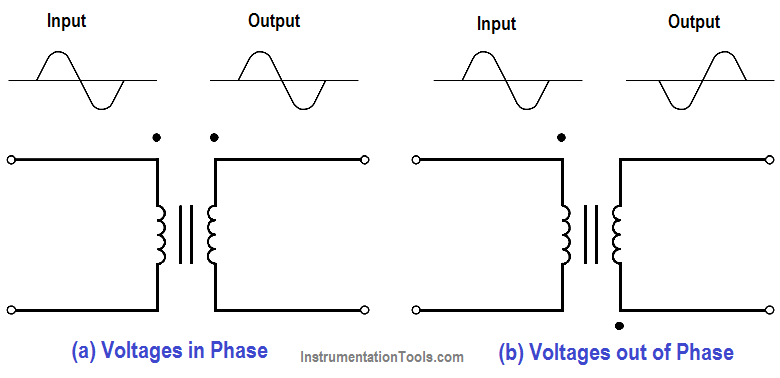
Figure 1 : Polarity of Transformer Coils

Don't Miss Our Updates
Be the first to get exclusive content straight to your email.
We promise not to spam you. You can unsubscribe at any time.
Invalid email address
You've successfully subscribed !

Continue Reading

DC Motor Theory
Transformer Operation Under No-Load
Magnetic Circuits
Calculate Power in Series RC Circuit
Single Phase Power Wiring Schemes
Applying Kirchhoff’s Voltage Law
Share This Article
Facebook Whatsapp Whatsapp LinkedIn Copy Link
Share
Leave a Comment

Leave a Reply Cancel reply

Your email address will not be published. Required fields are marked *

Stay Connected

128.3kFollowersLike
69.1kFollowersFollow
210kSubscribersSubscribe
38kFollowersFollow

Categories

Explore More

Inductance and Inductive Reactance
Shunt-Wound Motor Operation
AC Generation
Calculate Power in Parallel RC Circuit
Series-Wound DC Generators
Resistivity
Apparent Power, True Power, Reactive Power & Total Power
Impedance in RL Circuits

Keep Learning

Transformer Efficiency

Transformer Efficiency

Single Phase Motor Manual Controller

Motor Controllers

Series Parallel Circuit Analysis

Series – Parallel Circuit Analysis

Inductive Time Constant

Inductive Time Constant

Ohm Meter Circuit

Ohm Meter

Voltage Drop in a Series Circuit

Series Resistance

Carbon Atom

What is Electricity ?

Current in a Capacitor

Capacitance and Capacitive Reactance

Learn More

cat5e plenum cable

cat5e Plenum Cable History, Advantages and Disadvantages

Transducers MCQ

Transducers MCQ

Proximity Switch Questions and Sensors

62 Proximity Switch Questions and Answers

Electrical Engineers Basics

Basic Electrical Engineering Questions & Answers

Kv-value of a valve is determined by a standardised test

Calculate Flow Coefficient Kv of Solenoid Valve

Single Line Diagram (SLD) Example

Electrical Drawings

P&ID arrangement for Control Valves

P&ID Guidelines for Control Valves

Calculate Resistance from Temperature for RTD

RTD Calculator : Calculate Resistance from Temperature

Menu

  • About
  • Privacy Policy
  • Copyright

Quick Links

  • Learn PLC
  • Helping Hand
  • Part Time Job

YouTube Subscribe

Follow US
All rights reserved. Reproduction in whole or in part without written permission is prohibited.
Welcome Back!

Sign in to your account

Username or Email Address
Password

Lost your password?