Inst ToolsInst ToolsInst Tools
  • Courses
  • Videos
  • Q & A
    • Interview
      • Instrumentation
      • Electronics
      • Electrical
      • Practical Questions
    • MCQ
      • Instrumentation MCQ
      • Electrical MCQ
      • Electronics MCQ
      • Control Systems MCQ
      • Analog Electronics MCQ
      • Digital Electronics MCQ
      • Power Electronics MCQ
      • Microprocessor MCQ
      • Multiple Choice Questions
  • EE
    • Electronics
      • Electronics Q & A
      • Electronic Basics
      • Electronic Devices & Circuits
      • Electronics Animation
      • Digital Electronics
    • Electrical
      • Electrical Basics
      • Electrical Q & A
      • Power Electronics
      • Electrical Machines
      • Electrical Animation
      • Power Systems
      • Switchgear & Protection
      • Transmission & Distribution
  • Measure
    • Control Valves
    • Calibration
    • Temperature
    • Pressure
    • Flow
    • Level
    • Analyzers
    • Switches
    • Vibration
    • Solenoid Valve
  • Control
    • PLC Tutorials
    • Control Systems
    • Safety Instrumented System (SIS)
    • Communication
    • Fire & Gas System
  • More
    • Design
    • Tools
    • Animation
    • Basics
    • Formulas
    • Standards
    • TextBooks
    • Common
    • Software
    • Excel Tools
    • Erection & Commissioning
    • Process Fundamentals
    • Videos
    • Books
Search
All rights reserved. Reproduction in whole or in part without written permission is prohibited.
Font ResizerAa
Inst ToolsInst Tools
Font ResizerAa
  • Courses
  • PLC Tutorials
  • Control Systems
Search
  • Courses
  • Videos
  • Q & A
    • Interview
    • MCQ
  • EE
    • Electronics
    • Electrical
  • Measure
    • Control Valves
    • Calibration
    • Temperature
    • Pressure
    • Flow
    • Level
    • Analyzers
    • Switches
    • Vibration
    • Solenoid Valve
  • Control
    • PLC Tutorials
    • Control Systems
    • Safety Instrumented System (SIS)
    • Communication
    • Fire & Gas System
  • More
    • Design
    • Tools
    • Animation
    • Basics
    • Formulas
    • Standards
    • TextBooks
    • Common
    • Software
    • Excel Tools
    • Erection & Commissioning
    • Process Fundamentals
    • Videos
    • Books
Follow US
All rights reserved. Reproduction in whole or in part without written permission is prohibited.
Inst Tools > Blog > Practical Questions > Determine LRV and URV settings for the Level Transmitter

Determine LRV and URV settings for the Level Transmitter

Last updated: June 6, 2018 9:50 am
Editorial Staff
Practical Questions
1 Comment
Share
2 Min Read
SHARE

Determine LRV and URV settings for the Level Transmitter

Question :

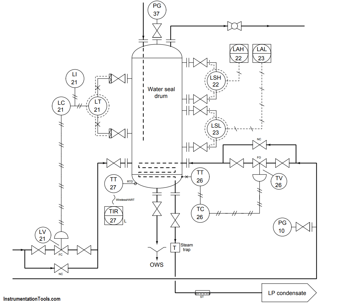
Determine the LRV and URV settings for the water seal drum level transmitter (LT-21), assuming the LRV point is at the lower nozzle and the URV point is at the upper nozzle (the two nozzles being 3 feet 8 inches apart from each other), and that the remote seal fill fluid has a specific gravity of 0.934:

Contents
Determine LRV and URV settings for the Level TransmitterQuestion :Answer :

water seal drum lever transmitter

Answer :

The elevation for this transmitter (i.e. the total differential pressure applied by the height of fill fluid on both sides) is equal to the total height difference between the remote seal diaphragms multiplied by the specific gravity of the fill fluid:

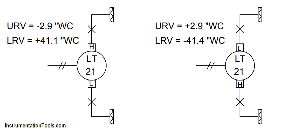
Pelevation = (44 in)(0.934) = 41.1 ”WC

In the LRV condition, this is the only pressure seen by the transmitter. Therefore, 41.1 ”WC is the appropriate LRV setting for this transmitter. If we assume that the “H” port of this DP transmitter connects to the lower nozzle, the LRV will be -44.1 ”WC. If we assume the “H” port connects to the upper nozzle, the LRV will be +41.4 ”WC.

In the URV condition, we have the exact same amount of elevation (the fill fluid inside the capillary tubes) but on the lower nozzle we have the hydrostatic pressure of 44 vertical inches of water (i.e. the water inside the seal drum). Thus, in the URV condition the transmitter sees a differential pressure of:

Pdifferential = 44” WC − 41.1 ”WC = 2.9 ”WC

If we assume the “H” port of this DP transmitter connects to the lower nozzle, the URV will be +2.9 ”WC.

If we assume the “H” port of this DP transmitter connects to the upper nozzle, the URV will be -2.9 ”WC.

Differential Transmitter capillary tubes

Don't Miss Our Updates
Be the first to get exclusive content straight to your email.
We promise not to spam you. You can unsubscribe at any time.
Invalid email address
You've successfully subscribed !

Continue Reading

Re-calibrate the Foxboro DP Pneumatic Transmitter
Calculate Density and Specific Gravity
pH Monitoring System Triggers an Alarm
Questions on Pressure Transmitter Calibration Setup
Practical Process Control System Questions & Answers – 8
Practical Process Control System Questions & Answers – 5
Share This Article
Facebook Copy Link Print
Share
1 Comment
  • N M P KUMAR UPPULURI says:
    April 13, 2018 at 9:10 am

    This is a very helpful information. It would be help full if you specify how to make a head correction for Level transmitters.

    Reply

Leave a Reply Cancel reply

Your email address will not be published. Required fields are marked *

Stay Connected

128.3kFollowersLike
69.1kFollowersFollow
208kSubscribersSubscribe
38kFollowersFollow

Categories

Explore More

What is the Simple Alternative Vessel Level Indication?
Solenoid Valves Practical Problems
Displacer Level Transmitter 5-point Calibration
Level Measurement Lab Exercise
Surface-mounted Water Pump
Compressor Emergency Shutdown Root Cause Analysis
Calculate the appropriate millivoltage values of a Thermocouple
Air Compressor Control Circuit Problem
Loop Powered Pressure Transmitter
Three-valve Manifold on Remote Seal DP Transmitter

Keep Learning

Level Transmitter trend

Identify Level Control Loop Tuning Problems

Inductive proximity switches

How to Connect Proximity Switch (Source Type) to Make LED ON ?

Practical Control Systems Questions & Answers

Practical Process Control System Questions & Answers – 1

Transmitter Questions

Practical Process Control System Questions & Answers – 4

Calculate the amount of voltage at Thermocouple

Calculate the Voltage across Voltmeters of Thermocouple

High Level Alarm of Distillation Process

Investigate High Level Alarm of Distillation Process

Pressure instruments example circuit

Motion-Balance and Force-Balance Instruments

Distillation Tower Displacer Level Instrument

Distillation Tower Displacer Level Instrument Check

Discover More

Asynchronous Motor Animation

Asynchronous Motor Animation

Fieldbus Transducer blocks

Foundation Fieldbus Standard Function Blocks

Spectrometers Questions and Answers

X-Ray Diffractometers Questions & Answers

RTD-standards

How to calculate the tolerance of a RTD sensor

Capacitive Level Switch Principle

Capacitive Level Switch Principle

Analyzers Questions and Answers

Silica Analyzer Questions & Answers

Dall Tube Flow Meter Working Principle

Dall Tube Flow Meter – Principle, Advantages, Disadvantages

Illumination Objective Questions

Illumination Objective Questions

Follow US
All rights reserved. Reproduction in whole or in part without written permission is prohibited.
Welcome Back!

Sign in to your account

Username or Email Address
Password

Lost your password?