Inst ToolsInst ToolsInst Tools
  • Courses
  • Automation
    • PLC
    • Control System
    • Safety System
    • Communication
    • Fire & Gas System
  • Instrumentation
    • Design
    • Pressure
    • Temperature
    • Flow
    • Level
    • Vibration
    • Analyzer
    • Control Valve
    • Switch
    • Calibration
    • Erection & Commissioning
  • Interview
    • Instrumentation
    • Electrical
    • Electronics
    • Practical
  • Q&A
    • Instrumentation
    • Control System
    • Electrical
    • Electronics
    • Analog Electronics
    • Digital Electronics
    • Power Electronics
    • Microprocessor
  • Request
Search
  • Books
  • Software
  • Projects
  • Process
  • Tools
  • Basics
  • Formula
  • Power Plant
  • Root Cause Analysis
  • Electrical Basics
  • Animation
  • Standards
  • 4-20 mA Course
  • Siemens PLC Course
Reading: Practical Process Control System Questions & Answers – 7
Share
Font ResizerAa
Inst ToolsInst Tools
Font ResizerAa
  • Courses
  • Design
  • PLC
  • Interview
  • Control System
Search
  • Courses
  • Automation
    • PLC
    • Control System
    • Safety System
    • Communication
    • Fire & Gas System
  • Instrumentation
    • Design
    • Pressure
    • Temperature
    • Flow
    • Level
    • Vibration
    • Analyzer
    • Control Valve
    • Switch
    • Calibration
    • Erection & Commissioning
  • Interview
    • Instrumentation
    • Electrical
    • Electronics
    • Practical
  • Q&A
    • Instrumentation
    • Control System
    • Electrical
    • Electronics
    • Analog Electronics
    • Digital Electronics
    • Power Electronics
    • Microprocessor
  • Request
Follow US
All rights reserved. Reproduction in whole or in part without written permission is prohibited.
Inst Tools > Blog > Practical Questions > Practical Process Control System Questions & Answers – 7

Practical Process Control System Questions & Answers – 7

Last updated: November 12, 2019 7:46 pm
Editorial Staff
Practical Questions
2 Comments
Share
2 Min Read
SHARE

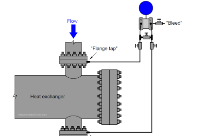
There is a problem somewhere in this liquid flow control system. The controller is in automatic mode, with a setpoint of 65%, yet the flow indicator and the flow controller both register 0.3%: (nearly) zero flow. A P&ID of the loop appears here:

liquid flow control system

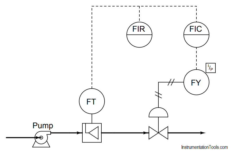
Explain how you would begin troubleshooting this system, and what possible faults could account for the controller not being able to maintain liquid flow at setpoint.

More Question

  1. Explain how you could divide this control system into distinct areas or zones which you may then begin to refer to when “dividing and conquering” the problem.

Answer :

One possible fault has to do with the control valve: perhaps something has happened to make it fail closed (loss of air supply, signal, etc.). Other possible problems include the following:

  • Pump not running (no source of fluid power to motivate flow)
  • Very poor controller tuning
  • Wrong controller action
  • Valve failed closed (loss of air supply, signal, etc.)
  • Transmitter failed, showing no flow when in fact there is

A good “first test” for troubleshooting the loop is to check the controller output: is it trying to open up the valve?

Share Your Answers via Comments

More Questions & Answers :
Practical Process Control System Questions & Answers – 1
Practical Process Control System Questions & Answers – 2
Practical Process Control System Questions & Answers – 3
Practical Process Control System Questions & Answers – 4
Practical Process Control System Questions & Answers – 5
Practical Process Control System Questions & Answers – 6
Practical Process Control System Questions & Answers – 7
Practical Process Control System Questions & Answers – 8
Practical Process Control System Questions & Answers – 9
Practical Process Control System Questions & Answers – 10
Don't Miss Our Updates
Be the first to get exclusive content straight to your email.
We promise not to spam you. You can unsubscribe at any time.
Invalid email address
You've successfully subscribed !

Continue Reading

What Affect the Pressure Measurement Accuracy of a Manometer?
Identify the Pressure Gauge Error
Instrument Lab Exercise – Ranging and Manometer Usage
Electronic Pressure Sensor with Bourdon Tube and LVDT
Questions on DP Transmitter Wet Leg Compensating Impulse Line
PLC Program to Control a Water Pump
Share This Article
Facebook Whatsapp Whatsapp LinkedIn Copy Link
Share
2 Comments
  • Mike Raines says:
    December 27, 2023 at 10:23 am

    It would be nice to know how the pump is controled?
    Is it by a VFD? Is it binary (on and off).
    If the valve is closed, with out an interlock with the pump, the pump will dead head and go out on overload. With out the pump interlock, the FIC will be lost.
    This is not a very well designed loop.

    Reply
  • Mike Raines says:
    December 27, 2023 at 10:24 am

    Sorry last e mail address had a typo.

    Reply

Leave a Reply Cancel reply

Your email address will not be published. Required fields are marked *

Stay Connected

128.3kFollowersLike
69.1kFollowersFollow
210kSubscribersSubscribe
38kFollowersFollow

Categories

Explore More

DP Transmitter Located 10 feet Beneath the Vessel
Determine the functions of Pressure Switches ?
Importance of Temperature in Remote Seal Pressure Transmitter
Programmable Logic Controller (PLC) Questions and Answers – 17
Smart DP Transmitter Flow Meter Calculations
Purpose of Stop in a Pressure Measuring Instrument
DP Transmitter Error Calculations
As per Process Conditions, Find out the Circuit Components Status ?

Keep Learning

Guided wave radar Measurement Principle

Instrument Salesperson Question

Pneumatic-Level-Transmitter-Value-Struck

Pneumatic Level Transmitter Value Struck?

Calculate Incident Power in Radar Level Measurement

Calculate Incident Power in Radar Level Measurement

Inclined Water Manometer

How much Pressure is applied to Inclined Water Manometer?

Problem on Weigh feeder

Problem on Weigh feeder

Pneumatic Transmitter

Pneumatic Level Transmitter Calibration Table

Calculate Total Hydrostatic Pressure at Bottom of Vessel

Calculate Total Hydrostatic Pressure at Bottom of Vessel

Which instrument is at fault in this system

Which Instrument is at Fault in this System?

Learn More

5-valve manifold

Pressure Transmitter Vent fittings

Difference Between Permittivity and Permeability

Difference Between Permittivity and Permeability

Capacitance Level Switch Working Principle

Capacitance Level Switch Working Principle

cut way synchronous motor

Synchronous Motors MCQ – Multiple Choice Questions

Actuators Questions and Answers

Actuators Questions and Answers

Real-time PLC Projects

Real-time PLC Projects – Industrial Automation

CO2 Absorber Graphics in DCS

CO2 Absorber Corroded Wall Thickness & Weld Building

What is a Inductive Proximity Switch

What is a Inductive Proximity Switch ?

Menu

  • About
  • Privacy Policy
  • Copyright

Quick Links

  • Learn PLC
  • Helping Hand
  • Part Time Job

YouTube Subscribe

Follow US
All rights reserved. Reproduction in whole or in part without written permission is prohibited.
Welcome Back!

Sign in to your account

Username or Email Address
Password

Lost your password?