Inst ToolsInst ToolsInst Tools
  • Courses
  • Automation
    • PLC
    • Control System
    • Safety System
    • Communication
    • Fire & Gas System
  • Instrumentation
    • Design
    • Pressure
    • Temperature
    • Flow
    • Level
    • Vibration
    • Analyzer
    • Control Valve
    • Switch
    • Calibration
    • Erection & Commissioning
  • Interview
    • Instrumentation
    • Electrical
    • Electronics
    • Practical
  • Q&A
    • Instrumentation
    • Control System
    • Electrical
    • Electronics
    • Analog Electronics
    • Digital Electronics
    • Power Electronics
    • Microprocessor
  • Request
Search
  • Books
  • Software
  • Projects
  • Process
  • Tools
  • Basics
  • Formula
  • Power Plant
  • Root Cause Analysis
  • Electrical Basics
  • Animation
  • Standards
  • 4-20 mA Course
  • Siemens PLC Course
Reading: Optical Torsion Meter Principle
Share
Notification Show More
Font ResizerAa
Inst ToolsInst Tools
Font ResizerAa
  • Courses
  • Design
  • PLC
  • Interview
  • Control System
Search
  • Courses
  • Automation
    • PLC
    • Control System
    • Safety System
    • Communication
    • Fire & Gas System
  • Instrumentation
    • Design
    • Pressure
    • Temperature
    • Flow
    • Level
    • Vibration
    • Analyzer
    • Control Valve
    • Switch
    • Calibration
    • Erection & Commissioning
  • Interview
    • Instrumentation
    • Electrical
    • Electronics
    • Practical
  • Q&A
    • Instrumentation
    • Control System
    • Electrical
    • Electronics
    • Analog Electronics
    • Digital Electronics
    • Power Electronics
    • Microprocessor
  • Request
Follow US
All rights reserved. Reproduction in whole or in part without written permission is prohibited.
Inst Tools > Blog > Common > Optical Torsion Meter Principle

Optical Torsion Meter Principle

Last updated: August 26, 2018 8:02 pm
Editorial Staff
Common
No Comments
Share
2 Min Read
SHARE

Basic Principle

Due to torque, an angular twist (angular displacement) occurs on the shaft between its ends. This angle of twist is measured by using optical means where in angular deflection of light rays is proportional to twist and hence the torque.

Construction of optical torsion meter

Optical Torsion Meter Principle

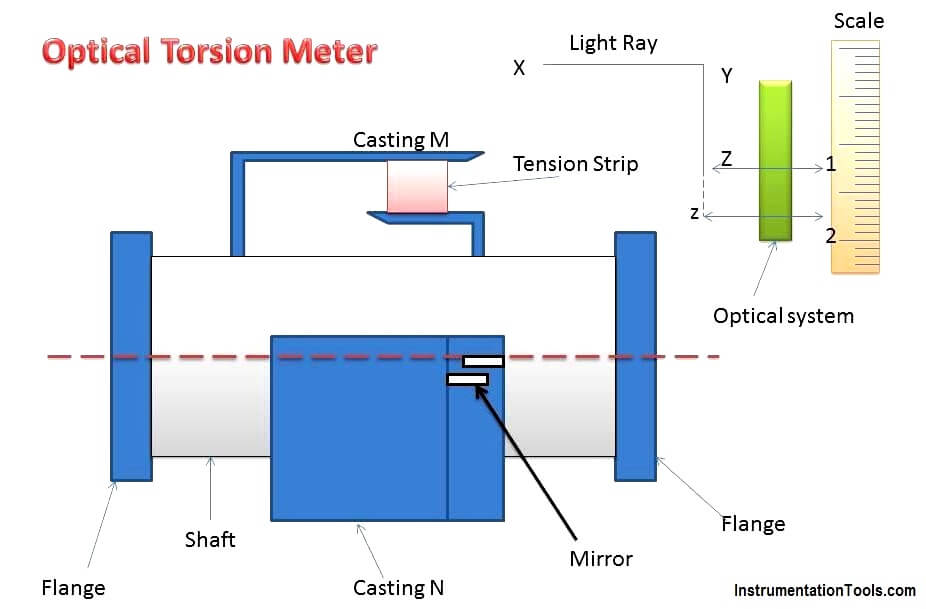
The main parts of an optical torsion meter as follows:

  1. A shaft is used on which two casting M and N are connected at a known distance.
  2. A tension strip linking the two castings.
  3. Two mirrors which are fitted and aligned on the castings.
  4. A light beam falling on the mirrors, an optical system and a torque calibrated scale.

Operation of optical torsion meter

When the shaft is transmitting torque, a relative movement occurs between castings M and N, and due to this, the mirrors will change position ( partial inclination between the two mirrors) since they are attached to the castings.

As the mirrors are constantly made to reflect a light beam on the torque calibrated scale, due to the changed position of the mirrors, there will be an angular deflection of the light rays which is measured from the calibrated scale.

This angular deflection of the light rays is proportional to the twist on the shaft (relative movement of casting M and N) and hence the torque of the shaft.

Applications of optical torsion meter

It is used in steam turbines and I.C engines

Don't Miss Our Updates
Be the first to get exclusive content straight to your email.
We promise not to spam you. You can unsubscribe at any time.
Invalid email address
You've successfully subscribed !

Continue Reading

What is a Thin Film Deposition System? How do they work?
Top Most Popular CNC Software Programs – A Comprehensive List
NPT Connection Measurement Size
What is Circular Chart Recorder?
Software Testing Projects – How to Approach the Process Effectively?
What is the Address Resolution Protocol? – Types of ARP
Share This Article
Facebook Whatsapp Whatsapp LinkedIn Copy Link
Share
Leave a Comment

Leave a Reply Cancel reply

Your email address will not be published. Required fields are marked *

Stay Connected

128.3kFollowersLike
69.1kFollowersFollow
210kSubscribersSubscribe
38kFollowersFollow

Categories

Explore More

The Most Significant Developments in Satellite Technology
Hydraulic Motor Forward and Reverse Control with Simulation
Saybolt Viscometer
5 Valve Manifold Operation
Difference between LVDT and RVDT?
Understanding the Chiller Maintenance – HVAC Tutorials
Pneumatic Instrumentation
Hydraulic versus Pneumatic Systems

Keep Learning

HVAC System

What is HVAC System?

Data Protection Tips

8 Data Protection Tips For Businesses And Individuals

Electrical Systems vs. Pneumatic Systems

Electrical Systems vs. Pneumatic Systems

Difference Between Skin Effect and Proximity Effect

Difference Between Skin Effect and Proximity Effect

Sugar Industry Logics

Mill Interlocks in the Sugar Industry

Physic Homework

Physic Homework Help – Tips to Find Professional Assistance

Essential Safety Tips for Glass Workers

Essential Safety Tips for Glass Workers

Supermarket HVAC Ventilation System

Supermarket Ventilation System – HVAC Basics

Learn More

Fundamentals of Digital Systems Quiz

200 Quiz Questions on Fundamentals of Digital Systems

Time Response Analysis

Approximation of Higher-Order Systems by Lower Order

Instrumentation Control Systems

What is Instrumentation Control System ?

TOC Analyzer Principle

Total Organic Carbon Analyzer Principle

Omron PLC Mixing System

Mixing Program with Timers and Counters in Omron PLC

Rotary Stem Valves

Rotary Stem Valves

Testing a defective transistor

Testing a Transistor with a Digital Multimeter

Electrical Machines Questions and Answers

Rotating Magnetic Field Multiple Choice Questions

Menu

  • About
  • Privacy Policy
  • Copyright

Quick Links

  • Learn PLC
  • Helping Hand
  • Part Time Job

YouTube Subscribe

Follow US
All rights reserved. Reproduction in whole or in part without written permission is prohibited.
Welcome Back!

Sign in to your account

Username or Email Address
Password

Lost your password?