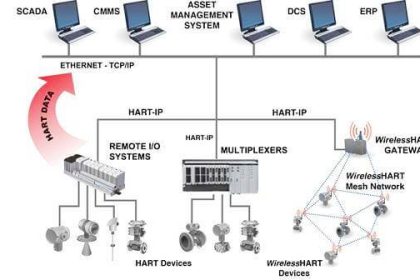
WirelessHART is a subset of the HART industrial instrument communication standard as of version 7, communicating process data over 2.4 GHz radio waves. Individual instruments communicate with a common “gateway” device serving as an interface between the wireless network and a wired network or a host control system.
In addition to this, though, individual WirelessHART devices also form links with one another, so that the network data routes look like a “mesh” with all nearby nodes interconnected in addition to connecting with the gateway:
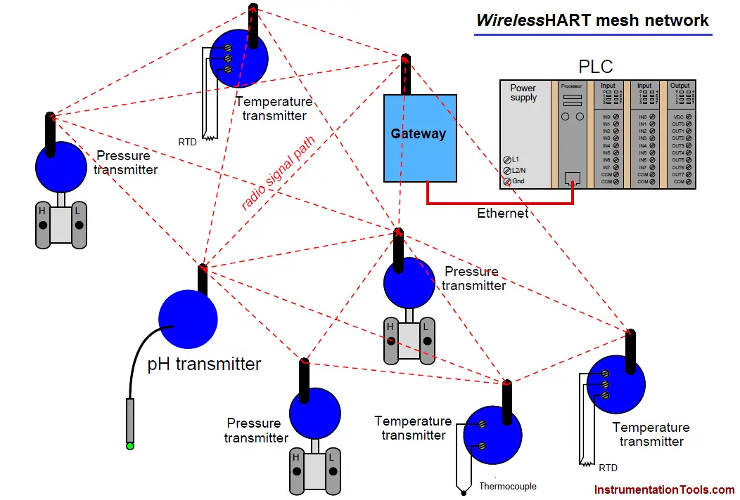
In a mesh network, devices (nodes) perform double-duty as repeaters to relay data from other instruments to the gateway as needed. In other words, data transmitted from one WirelessHART instrument may not be directly received by the gateway device if that path is blocked or too far away. Instead, the data may “hop” from one device to another nearby, which then re-broadcasts that information to the gateway via a clearer path.
The purpose of a mesh network is to provide redundant data pathways in case of device failure or changes in the environment interrupting radio communication between devices. In this way, data packets may be re-routed to the gateway if the shortest route fails, in a manner similar to how Terminal Control Protocol (TCP) and Internet Protocol (IP) work together to route data segments from source to destination over the “mesh” of the Internet. This feature is often referred to in WirelessHART technical literature as the self-healing property of the mesh network.
According to the HART Foundation, reliability for a well-designed WirelessHART mesh network is 99.7300204% minimum, and typically greater than 99.9999998%.
With each WirelessHART field instrument capable of functioning as a radio repeater, the potential exists to form wireless networks larger in size than the maximum broadcast/reception range of any one device. This illustration shows what is possible:
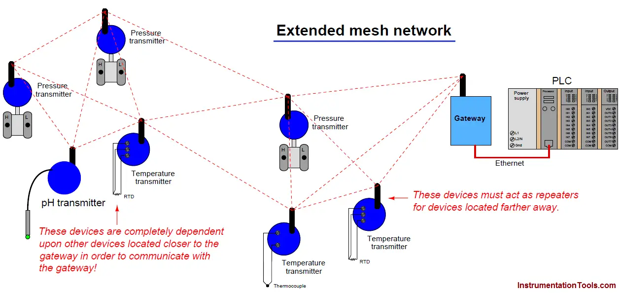
Note : Some obvious connecting paths between field devices have been omitted from this illustration if the path length exceeds a certain maximum distance. As you can see, the instruments in the far-left cluster must rely on data packet relaying by instruments closer to the gateway, since they themselves are too far away from the gateway to directly communicate.
An important consideration when planning a WirelessHART network is battery life. With the main purpose of wireless field instruments being the elimination of wired connections to the host system, the field instruments cannot rely on a host system for their electrical power needs. Lithium-based batteries currently fulfill this role as the primary power source, with life expectancies of several years.
Interestingly, the amount of energy required by a WirelessHART device to transmit radiofrequency data is small compared to the energy required to power its essential instrument functions (e.g. pressure measurement, temperature measurement). This means a WirelessHART device operating as a radio repeater (in addition to being a measurement device) adds little burden to its battery.
Perhaps the greatest challenge in sustaining any wireless field instrument network is ensuring network integrity despite unending changes in the physical environment around the instruments. Remember that this is an industrial, field-instrument wireless network designed to be installed in less-than-ideal physical environments.
These wireless devices must somehow reliably communicate with each other despite interference from high-power electrical devices (e.g. variable-frequency motor drive units), while mounted on or near metal objects such as girders, pipes, pipe racks, large vessels, motors, enclosures, shelters, and electrical conduits.
Even the ground of an industrial environment can be an impediment to robust radio communication: steel-reinforced concrete and electrical grounding grids form what is essentially a solid “ground plane” that will interfere with WirelessHART devices mounted too close to ground level.
Added to all this spatial complexity is the continual presence of large vehicles and other moving machines (cranes, forklifts, man lifts, etc.). It is not uncommon for scaffolding to be temporarily erected for maintenance work in industrial areas, presenting yet one more obstacle for RF signals.
In answer to these challenges is an integral and essential component of a WirelessHART network called the Network Manager : an advanced digital algorithm usually executed by the network gateway’s microprocessor. The purpose of the Network Manager is to manage the details of the network automatically, “tuning” various parameters for optimum reliability and data throughput.
Among other tasks, the Network Manager assigns “timeslots” for individual devices to transmit, determines the frequency-hopping schedule, detects and authenticates new devices added to the network, dynamically adjusts device transmission power, and selects alternative routes between devices.
In a sense, the Network Manager in a WirelessHART network continually audits and tunes the RF system in an attempt to maximize reliability.
The Network Manager’s functionality does not substitute for good planning during the design phase of the WirelessHART network, but it does eliminate the need for a human technician or engineer to continuously monitor the network’s performance and make the small adjustments necessary to compensate for changing conditions.
When changes occur in a WirelessHART network that cannot be compensated by the Network Manager, the real-time statistics provided by the Network Manager are invaluable to the technician or engineer assigned to update the network.


Another point that needs to be addressed is the bandwidth of the network.
This isn’t a huge issue until you have an extended mesh network and the isolated transmitters are forced to bottleneck through one or two paths. One thing you can see is transmitters fighting each other for space on the network and drop outs may occur.
You can open up some bandwidth by increasing the time between updates for the transmitters being affected.
I am an electronic researcher, I will be appreciated if you inform me , how can I get in touch with your researchment lab,
because of my new individual design for X ray generation.
I like to send my proposal details to them for invetigation , its evidently I will provide them for all tech.information which
will be requested.