Inst ToolsInst ToolsInst Tools
  • Ask
  • Courses
  • Videos
  • Q & A
    • Interview
      • Instrumentation
      • Electronics
      • Electrical
      • Practical Questions
    • MCQ
      • Instrumentation MCQ
      • Electrical MCQ
      • Electronics MCQ
      • Control Systems MCQ
      • Analog Electronics MCQ
      • Digital Electronics MCQ
      • Power Electronics MCQ
      • Microprocessor MCQ
      • Multiple Choice Questions
  • EE
    • Electronics
      • Electronics Q & A
      • Electronic Basics
      • Electronic Devices & Circuits
      • Electronics Animation
      • Digital Electronics
    • Electrical
      • Electrical Basics
      • Electrical Q & A
      • Power Electronics
      • Electrical Machines
      • Electrical Animation
      • Power Systems
      • Switchgear & Protection
      • Transmission & Distribution
  • Measure
    • Control Valves
    • Calibration
    • Temperature
    • Pressure
    • Flow
    • Level
    • Analyzers
    • Switches
    • Vibration
    • Solenoid Valve
  • Control
    • PLC Tutorials
    • Control Systems
    • Safety Instrumented System (SIS)
    • Communication
    • Fire & Gas System
  • More
    • Design
    • Tools
    • Animation
    • Basics
    • Formulas
    • Standards
    • TextBooks
    • Common
    • Software
    • Excel Tools
    • Erection & Commissioning
    • Process Fundamentals
    • Videos
    • Books
Search
All rights reserved. Reproduction in whole or in part without written permission is prohibited.
Reading: Testing a Transistor with a Digital Multimeter
Share
Notification Show More
Font ResizerAa
Inst ToolsInst Tools
Font ResizerAa
  • Courses
  • PLC Tutorials
  • Control Systems
Search
  • Ask
  • Courses
  • Videos
  • Q & A
    • Interview
    • MCQ
  • EE
    • Electronics
    • Electrical
  • Measure
    • Control Valves
    • Calibration
    • Temperature
    • Pressure
    • Flow
    • Level
    • Analyzers
    • Switches
    • Vibration
    • Solenoid Valve
  • Control
    • PLC Tutorials
    • Control Systems
    • Safety Instrumented System (SIS)
    • Communication
    • Fire & Gas System
  • More
    • Design
    • Tools
    • Animation
    • Basics
    • Formulas
    • Standards
    • TextBooks
    • Common
    • Software
    • Excel Tools
    • Erection & Commissioning
    • Process Fundamentals
    • Videos
    • Books
Follow US
All rights reserved. Reproduction in whole or in part without written permission is prohibited.
Inst Tools > Blog > Electronic Basics > Testing a Transistor with a Digital Multimeter

Testing a Transistor with a Digital Multimeter

Last updated: April 30, 2018 9:18 am
Editorial Staff
Electronic Basics Electronic Devices & Circuits
1 Comment
Share
6 Min Read
SHARE

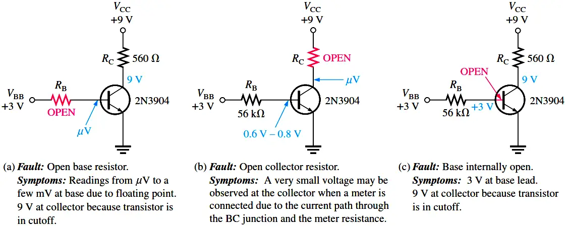
Several faults that can occur in the circuit and the accompanying symptoms are illustrated in Below Figure. Symptoms are shown in terms of measured voltages that are incorrect. If a transistor circuit is not operating correctly, it is a good idea to verify that VCC and ground are connected and operating. A simple check at the top of the collector resistor and at the collector itself will quickly ascertain if VCC is present and if the transistor is conducting normally or is in cutoff or saturation.

If it is in cutoff, the collector voltage will equal VCC; if it is in saturation, the collector voltage will be near zero. Another faulty measurement can be seen if there is an open in the collector path. The term floating point refers to a point in the circuit that is not electrically connected to ground or a “solid” voltage. Normally, very small and sometimes fluctuating voltages in the mV to low mV range are generally measured at floating points. The faults in Below Figure are typical but do not represent all possible faults that may occur.

Testing a Transistor with a Digital Multimeter

Testing a Transistor with Multimeter

Testing a Transistor with a DMM

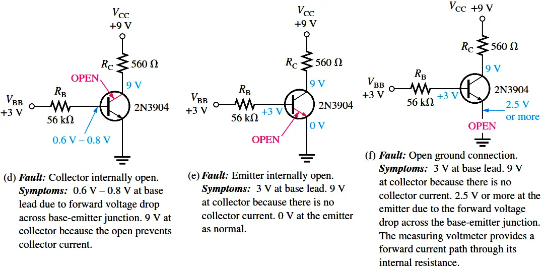
A digital multimeter can be used as a fast and simple way to check a transistor for open or shorted junctions. For this test, you can view the transistor as two diodes connected as shown in Below Figure for both npn and pnp transistors. The base-collector junction is one diode and the base-emitter junction is the other.

Testing a Transistor with a DMM

A good diode will show an extremely high resistance (or open) with reverse bias and a very low resistance with forward bias. A defective open diode will show an extremely high resistance (or open) for both forward and reverse bias. A defective shorted or resistive diode will show zero or a very low resistance for both forward and reverse bias. An open diode is the most common type of failure. Since the transistor pn junctions are, in effect diodes, the same basic characteristics apply.

The DMM Diode Test Position

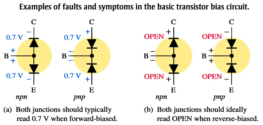
Many digital multimeters (DMMs) have a diode test position that provides a convenient way to test a transistor. A typical DMM, as shown in Below Figure, has a small diode symbol to mark the position of the function switch. When set to diode test, the meter provides an internal voltage sufficient to forward-bias and reverse-bias a transistor junction.

Transistor testing

When the Transistor Is Not Defective

In Figure (a), the red (positive) lead of the meter is connected to the base of an npn transistor and the black (negative) lead is connected to the emitter to forward-bias the base-emitter junction. If the junction is good, you will get a reading of between approximately 0.6 V and 0.8 V, with 0.7 V being typical for forward bias. In Figure (b), the leads are switched to reverse-bias the base-emitter junction, as shown. If the transistor is working properly, you will typically get an OL indication. The process just described is repeated for the base-collector junction as shown in Figure (c) and (d). For a pnp transistor, the polarity of the meter leads are reversed for each test.

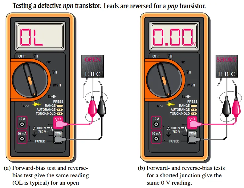
When the Transistor Is Defective

When a transistor has failed with an open junction or internal connection, you get an open circuit voltage reading (OL) for both the forward-bias and the reverse-bias conditions for that junction, as illustrated in Figure (a). If a junction is shorted, the meter reads 0 V in both forward- and reverse-bias tests, as indicated in part (b). Some DMMs provide a test socket on their front panel for testing a transistor for the hFE (βDC) value. If the transistor is inserted improperly in the socket or if it is not functioning properly due to a faulty junction or internal connection, a typical meter will flash a 1 or display a 0. If a value of βDC within the normal range for the specific transistor is displayed, the device is functioning properly. The normal range of βDC can be determined from the datasheet.

Checking a Transistor with the OHMs Function

DMMs that do not have a diode test position or an hFE socket can be used to test a transistor for open or shorted junctions by setting the function switch to an OHMs range. For the forward-bias check of a good transistor pn junction, you will get a resistance reading that can vary depending on the meter’s internal battery. Many DMMs do not have sufficient voltage on the OHMs range to fully forward-bias a junction, and you may get a reading of from several hundred to several thousand ohms.

For the reverse-bias check of a good transistor, you will get an out-of-range indication on most DMMs because the reverse resistance is too high to measure. An out-of-range indication may be a flashing 1 or a display of dashes, depending on the particular DMM.

Even though you may not get accurate forward and reverse resistance readings on a DMM, the relative readings are sufficient to indicate a properly functioning transistor PN junction. The out-of-range indication shows that the reverse resistance is very high, as you expect. The reading of a few hundred to a few thousand ohms for forward bias indicates that the forward resistance is small compared to the reverse resistance, as you expect.

Testing a defective transistor

Don't Miss Our Updates
Be the first to get exclusive content straight to your email.
We promise not to spam you. You can unsubscribe at any time.
Invalid email address
You've successfully subscribed !
What is PCB Corrosion? Electronic Boards Corrosion Prevention
Full Wave Rectifier
Factors Affecting Inductance
Optoisolator Working Principle
Diodes Voltage Tripler
Share This Article
Facebook Whatsapp Whatsapp LinkedIn Copy Link
Share
1 Comment
  • trevor says:
    August 14, 2016 at 9:55 pm

    good engineering stuff

    Reply

Leave a Reply Cancel reply

Your email address will not be published. Required fields are marked *

Stay Connected

128.3kFollowersLike
69.1kFollowersFollow
208kSubscribersSubscribe
38kFollowersFollow

Categories

Recent Comments

  • Guifty Shimica on Top Non-PLC Certification Courses for Automation Professionals
  • Guifty Shimica on Top Non-PLC Certification Courses for Automation Professionals
  • MIHARITSOA Aina Sitraka on Top Non-PLC Certification Courses for Automation Professionals
  • Vaishnavi on Free Instrumentation Course for Trainee Engineers

Related Articles

Transistor Biasing

Transistor Biasing

Cathode Ray Tube Deflection System

Cathode Ray Tube Deflection System

Current Limiting Resistor

Resistors Principle & Applications

How a Multi Color LED Works

How a Multi Color LED Works ?

Motor contactors

What is Contactor ?

How are Silicon Chips Disposed?

How are Silicon Chips Disposed?

Zener Diode Regulator

Zener Diode Voltage Regulators

half-wave-rectifier-working-animation

Half Wave Rectifier Principle

More Articles

Structured Text Automatic Gate Logic

Structured Text PLC Programming for Automatic Gate Control

Fieldbus Control Loop

Foundation Fieldbus Communication Management

Redundant system communication cable

What is Interface Module in Siemens PLC?

Voltage Control Methods at Distribution System

Voltage Control Methods at Distribution System

Quiz Questions for Instrumentation and Control Professionals

200 Quiz Questions for Instrumentation and Control Professionals

Level Loop Troubleshooting

Identify Faults in PID Control Loop

Chromatography Questions & Answers

Operation of Chromatography Questions & Answers

High Voltage and Power System Stability Interview Questions

High Voltage and Power System Stability Interview Questions

Follow US
All rights reserved. Reproduction in whole or in part without written permission is prohibited.
Welcome Back!

Sign in to your account

Username or Email Address
Password

Lost your password?