Inst ToolsInst ToolsInst Tools
  • Courses
  • Videos
  • Q & A
    • Interview
      • Instrumentation
      • Electronics
      • Electrical
      • Practical Questions
    • MCQ
      • Instrumentation MCQ
      • Electrical MCQ
      • Electronics MCQ
      • Control Systems MCQ
      • Analog Electronics MCQ
      • Digital Electronics MCQ
      • Power Electronics MCQ
      • Microprocessor MCQ
      • Multiple Choice Questions
  • EE
    • Electronics
      • Electronics Q & A
      • Electronic Basics
      • Electronic Devices & Circuits
      • Electronics Animation
      • Digital Electronics
    • Electrical
      • Electrical Basics
      • Electrical Q & A
      • Power Electronics
      • Electrical Machines
      • Electrical Animation
      • Power Systems
      • Switchgear & Protection
      • Transmission & Distribution
  • Measure
    • Control Valves
    • Calibration
    • Temperature
    • Pressure
    • Flow
    • Level
    • Analyzers
    • Switches
    • Vibration
    • Solenoid Valve
  • Control
    • PLC Tutorials
    • Control Systems
    • Safety Instrumented System (SIS)
    • Communication
    • Fire & Gas System
  • More
    • Design
    • Tools
    • Animation
    • Basics
    • Formulas
    • Standards
    • TextBooks
    • Common
    • Software
    • Excel Tools
    • Erection & Commissioning
    • Process Fundamentals
    • Videos
    • Books
Search
All rights reserved. Reproduction in whole or in part without written permission is prohibited.
Reading: Basics of Transistors
Share
Notification Show More
Font ResizerAa
Inst ToolsInst Tools
Font ResizerAa
  • Courses
  • PLC Tutorials
  • Control Systems
Search
  • Courses
  • Videos
  • Q & A
    • Interview
    • MCQ
  • EE
    • Electronics
    • Electrical
  • Measure
    • Control Valves
    • Calibration
    • Temperature
    • Pressure
    • Flow
    • Level
    • Analyzers
    • Switches
    • Vibration
    • Solenoid Valve
  • Control
    • PLC Tutorials
    • Control Systems
    • Safety Instrumented System (SIS)
    • Communication
    • Fire & Gas System
  • More
    • Design
    • Tools
    • Animation
    • Basics
    • Formulas
    • Standards
    • TextBooks
    • Common
    • Software
    • Excel Tools
    • Erection & Commissioning
    • Process Fundamentals
    • Videos
    • Books
Follow US
All rights reserved. Reproduction in whole or in part without written permission is prohibited.
Inst Tools > Blog > Electronic Devices & Circuits > Basics of Transistors

Basics of Transistors

Last updated: September 27, 2016 4:05 pm
Editorial Staff
Electronic Devices & Circuits
No Comments
Share
5 Min Read
SHARE

A transistor consists of two pn junctions formed by *sandwiching either p-type or n-type semicon-ductor between a pair of opposite types. Accordingly ; there are two types of transistors, namely;

(i)  n-p-n transistor                                (ii)  p-n-p transistor

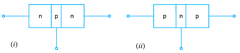
An n–p–n transistor is composed of two n-type semiconductors separated by a thin section of p-type as shown in Fig. (i). However, a p-n-p transistor is formed by two p-sections separated by a thin section of n-type as shown in Fig. (ii).

transistor symbols

In each type of transistor, the following points may be noted :

(i) These are two pn junctions. Therefore, a transistor may be regarded as a combination of two diodes connected back to back.

(ii)  There are three terminals, one taken from each type of semiconductor.

(iii) The middle section is a very thin layer. This is the most important factor in the function of a transistor.

Transistor Terminals

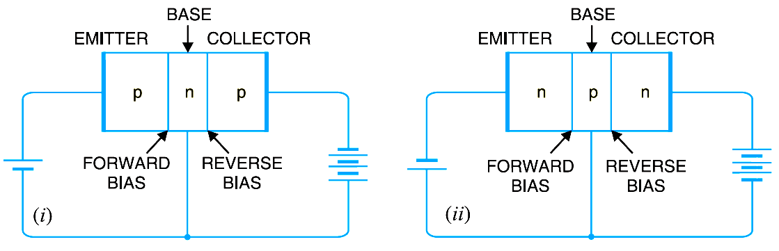
A transistor (pnp or npn) has three sections of doped semiconductors. The section on one side is the emitter and the section on the opposite side is the collector. The middle section is called the base and forms two junctions between the emitter and collector.

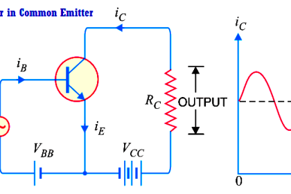
(i) Emitter. The section on one side that supplies charge carriers (electrons or holes) is called the emitter. The emitter is always forward biased w.r.t. base so that it can supply a large number of *majority carriers. In Below Fig. (i), the emitter (p-type) of pnp transistor is forward biased and supplies hole charges to its junction with the base. Similarly, in Below Fig. (ii), the emitter (n-type) of npn transistor has a forward bias and supplies free electrons to its junction with the base.

(ii) Collector. The section on the other side that collects the charges is called the collector. The collector is always reverse biased. Its function is to remove charges from its junction with the base. In Below Fig (i), the collector (p-type) of pnp transistor has a reverse bias and receives hole charges that flow in the output circuit. Similarly, in Below Fig. (ii), the collector (n-type) of npn transistor has reverse bias and receives electrons.

(iii) Base. The middle section which forms two pn-junctions between the emitter and collector is called the base. The base-emitter junction is forward biased, allowing low resistance for the emit-ter circuit. The base-collector junction is reverse biased and provides high resistance in the collector circuit.

transistor-terminals

Facts about the Transistor

Before discussing transistor action, it is important that the reader may keep in mind the following facts about the transistor :

(i) The transistor has three regions, namely ; emitter, base and collector. The base is much thinner than the emitter while **collector is wider than both as shown in Fig. However, for the sake of convenience, it is customary to show emitter and collector to be of equal size.

(ii) The emitter is heavily doped so that it can inject a large number of charge carriers (electrons or holes) into the base. The base is lightly doped and very thin ; it passes most of the emitter injected charge carriers to the collector. The collector is moderately doped.

(iii) The transistor has two pn junctions i.e. it is like two diodes. The junction between emitter and base may be called emitter-base diode or simply the emitter diode. The junction between the base and collector may be called collector-base diode or simply collector diode.

(iv) The emitter diode is always forward biased whereas collector diode is always reverse biased.

(v) The resistance of emitter diode (forward biased) is very small as compared to collector diode (reverse biased). Therefore, forward bias applied to the emitter diode is generally very small whereas reverse bias on the collector diode is much higher.

Don't Miss Our Updates
Be the first to get exclusive content straight to your email.
We promise not to spam you. You can unsubscribe at any time.
Invalid email address
You've successfully subscribed !

Recommended Articles

Amplifiers Questions & Answers
Bipolar Junction Transistor Construction
Diodes Voltage Quadrupler
Types of Resistors
Full Wave Bridge Rectifier Operation
Seven Segment Display Working Principle
Share This Article
Facebook Whatsapp Whatsapp LinkedIn Copy Link
Share
Leave a Comment

Leave a Reply Cancel reply

Your email address will not be published. Required fields are marked *

Stay Connected

128.3kFollowersLike
69.1kFollowersFollow
208kSubscribersSubscribe
38kFollowersFollow

Categories

Recent Comments

  • William Snyder on Top Non-PLC Certification Courses for Automation Professionals
  • Kamli on Top Free PLC Software
  • Guifty Shimica on Top Non-PLC Certification Courses for Automation Professionals
  • Guifty Shimica on Top Non-PLC Certification Courses for Automation Professionals

Related Articles

Applications of Photo diodes

Applications of Photo diodes

diode-clamper-circuit

Full Wave Voltage Doubler using Diodes

Transistors Questions & Answers

Transistors Questions & Answers

pn-junction-energy-diagrams

Energy Diagrams of PN Junction & Depletion Region

Current Divider Rule

Current Divider Rule

phototransistor symbols

Phototransistor Working Principle

example-of-KCL

What is Kirchhoff’s Current Law

Diode-testing-with-multimeter

How to Test a Diode using Multimeter

More Articles

Resistor-Color-Code-Chart

Resistor Color Code Animation

CRA Module in Schneider PLC

CRA Module in Schneider PLC – Remote IO Adapter Module

Short Circuit and Open Circuit

Short Circuit and Open Circuit

Electrical Machines Questions and Answers

Double Excited Magnetic System Quiz

An Indian Plants all turbines’ low Vacuum

An Indian Plants all turbines’ low Vacuum & Saudi Plant turbo-compressor only

What is Gas Leak Detection System

What is Gas Leak Detection System ?

Automotive Rail Rapid Transit

Automotive Rail Rapid Transit

Difference Between RS232 and RS485

Difference Between RS232 and RS485

Follow US
All rights reserved. Reproduction in whole or in part without written permission is prohibited.
Welcome Back!

Sign in to your account

Username or Email Address
Password

Lost your password?