Inst ToolsInst ToolsInst Tools
  • Courses
  • Automation
    • PLC
    • Control System
    • Safety System
    • Communication
    • Fire & Gas System
  • Instrumentation
    • Design
    • Pressure
    • Temperature
    • Flow
    • Level
    • Vibration
    • Analyzer
    • Control Valve
    • Switch
    • Calibration
    • Erection & Commissioning
  • Interview
    • Instrumentation
    • Electrical
    • Electronics
    • Practical
  • Q&A
    • Instrumentation
    • Control System
    • Electrical
    • Electronics
    • Analog Electronics
    • Digital Electronics
    • Power Electronics
    • Microprocessor
  • Request
Search
  • Books
  • Software
  • Projects
  • Process
  • Tools
  • Basics
  • Formula
  • Power Plant
  • Root Cause Analysis
  • Electrical Basics
  • Animation
  • Standards
  • 4-20 mA Course
  • Siemens PLC Course
Reading: Define Normal Status of a Process Switch ?
Share
Font ResizerAa
Inst ToolsInst Tools
Font ResizerAa
  • Courses
  • Design
  • PLC
  • Interview
  • Control System
Search
  • Courses
  • Automation
    • PLC
    • Control System
    • Safety System
    • Communication
    • Fire & Gas System
  • Instrumentation
    • Design
    • Pressure
    • Temperature
    • Flow
    • Level
    • Vibration
    • Analyzer
    • Control Valve
    • Switch
    • Calibration
    • Erection & Commissioning
  • Interview
    • Instrumentation
    • Electrical
    • Electronics
    • Practical
  • Q&A
    • Instrumentation
    • Control System
    • Electrical
    • Electronics
    • Analog Electronics
    • Digital Electronics
    • Power Electronics
    • Microprocessor
  • Request
Follow US
All rights reserved. Reproduction in whole or in part without written permission is prohibited.
Inst Tools > Blog > Practical Questions > Define Normal Status of a Process Switch ?

Define Normal Status of a Process Switch ?

Last updated: August 15, 2017 10:22 am
Editorial Staff
Practical Questions
No Comments
Share
2 Min Read
SHARE

Switches, whether they be hand-actuated or actuated by a physical process, come in two varieties: normally-open (NO) and normally-closed (NC). You are probably accustomed to seeing both types of switch represented in pushbutton form on schematic diagrams:

Normally Open Switch and Normally Closed Switch

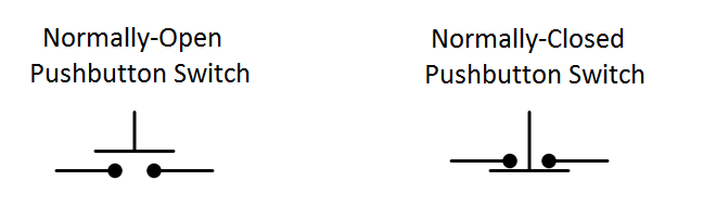
Normally-open pushbutton switches close (pass current) when actuated (pressed). When un-actuated, they return to their “normal” (open) state.

Normally-closed pushbutton switches are just the opposite: they open (stop current) when actuated (pressed) and return to their “normal” (closed, passing current) state when un-actuated.

This is simple enough to comprehend: the “normal” status of a momentary-contact pushbutton switch is the state it is in when no one is touching it. When pressed, the pushbutton switch goes to the other (opposite) state.

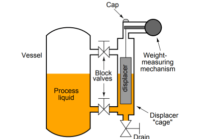
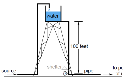
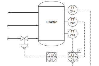
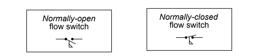
Things get more confusing, though, when we examine process switches, such as pressure switches, level switches, temperature switches, and flow switches:

Instrument Switch Status

Flow Switch Status

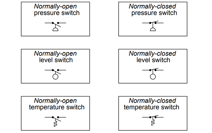
Define “normal” for each of these process switches. In other words, explain what condition(s) each process switch must be in to ensure it is in the “normal” state; and conversely, what condition(s) need to be applied to each switch to force it into its other state.

Answer :

The “normal” condition for a process switch is the condition of least stimulus.

For example:

  • A pressure switch will be in its “normal” state when there is minimum pressure applied
  • A level switch will be in its “normal” state when there is no level detected by the switch
  • A temperature switch will be in its “normal” state when it is cold
  • A flow switch will be in its “normal” state when there is no flow detected by the switch

Share Your Answers / comments.

Credits : by Tony R. Kuphaldt – under CC BY 1.0

Don't Miss Our Updates
Be the first to get exclusive content straight to your email.
We promise not to spam you. You can unsubscribe at any time.
Invalid email address
You've successfully subscribed !

Continue Reading

Calculate the Thermocouple Output millivolts
How much Pressure is applied to Inclined Water Manometer?
How Overload Heaters used to Automatically Shut the Motor OFF ?
Questions on Radar LT Loop Diagram
Pressure Switch Questions
Practical Process Control System Questions & Answers – 3
Share This Article
Facebook Whatsapp Whatsapp LinkedIn Copy Link
Share
Leave a Comment

Leave a Reply Cancel reply

Your email address will not be published. Required fields are marked *

Stay Connected

128.3kFollowersLike
69.1kFollowersFollow
210kSubscribersSubscribe
38kFollowersFollow

Categories

Explore More

Calculate 0%, 50%, and 100% Calibration Points for ΔP transmitter
Calculate Hydraulic Pressure of a Process Vessel
DP Transmitter Calibration Errors
Inspecting the Trends of PV and SP on a Process Chart Recorder
Calculate the Temperature of 4 Wire RTD
Programmable Logic Controller (PLC) Questions and Answers – 2
Programmable Logic Controller (PLC) Questions and Answers – 6
Troubleshoot Allen Bradley PLC Logic

Keep Learning

Guided-wave Radar Asset Management Parameters

Guided-wave Radar Asset Management Parameters

Relay ladder diagram example

How to Draw a Schematic Diagram ?

Calculate the Magnitude of Hydrostatic Pressure

Calculate the Magnitude of Hydrostatic Pressure

Allen-Bradley MicroLogix PLC Wiring

Programmable Logic Controller (PLC) Questions and Answers – 8

Which instrument is faulty

Which Instrument is Faulty? Transmitter, Recorder, or Controller

water filter level control system

Practical Process Control System Questions & Answers – 6

Calculate Density and Specific Gravity

Calculate Density and Specific Gravity

Questions on Pneumatic Control Loop

Questions on Pneumatic Control Loop

Learn More

solenoid valves trip

Identify Solenoid Valves Energized or de-energized?

Basic Process Control Loop

Introduction to Industrial Instrumentation

conductivity transmitter

Conductivity Transmitter Calibration Procedure

Electric Motor Actuators

What is Motor Actuator ?

Conveyor Sorting Omron PLC Programming

CX-Programmer Products Sorting & Counting – Omron PLC

Power Outlet

How does Electrical Power Outlet Work?

Symbol of Transistor

Power Transistor – Structure, Biasing, Characteristics, Advantages

Control system architecture diagrams

Vendor Document for Project Systems Architecture

Menu

  • About
  • Privacy Policy
  • Copyright

Quick Links

  • Learn PLC
  • Helping Hand
  • Part Time Job

YouTube Subscribe

Follow US
All rights reserved. Reproduction in whole or in part without written permission is prohibited.
Welcome Back!

Sign in to your account

Username or Email Address
Password

Lost your password?