Inst ToolsInst ToolsInst Tools
  • Courses
  • Videos
  • Q & A
    • Interview
      • Instrumentation
      • Electronics
      • Electrical
      • Practical Questions
    • MCQ
      • Instrumentation MCQ
      • Electrical MCQ
      • Electronics MCQ
      • Control Systems MCQ
      • Analog Electronics MCQ
      • Digital Electronics MCQ
      • Power Electronics MCQ
      • Microprocessor MCQ
      • Multiple Choice Questions
  • EE
    • Electronics
      • Electronics Q & A
      • Electronic Basics
      • Electronic Devices & Circuits
      • Electronics Animation
      • Digital Electronics
    • Electrical
      • Electrical Basics
      • Electrical Q & A
      • Power Electronics
      • Electrical Machines
      • Electrical Animation
      • Power Systems
      • Switchgear & Protection
      • Transmission & Distribution
  • Measure
    • Control Valves
    • Calibration
    • Temperature
    • Pressure
    • Flow
    • Level
    • Analyzers
    • Switches
    • Vibration
    • Solenoid Valve
  • Control
    • PLC Tutorials
    • Control Systems
    • Safety Instrumented System (SIS)
    • Communication
    • Fire & Gas System
  • More
    • Design
    • Tools
    • Animation
    • Basics
    • Formulas
    • Standards
    • TextBooks
    • Common
    • Software
    • Excel Tools
    • Erection & Commissioning
    • Process Fundamentals
    • Videos
    • Books
Search
All rights reserved. Reproduction in whole or in part without written permission is prohibited.
Reading: Photodiode as Variable Resistance Device
Share
Notification Show More
Font ResizerAa
Inst ToolsInst Tools
Font ResizerAa
  • Courses
  • PLC Tutorials
  • Control Systems
Search
  • Courses
  • Videos
  • Q & A
    • Interview
    • MCQ
  • EE
    • Electronics
    • Electrical
  • Measure
    • Control Valves
    • Calibration
    • Temperature
    • Pressure
    • Flow
    • Level
    • Analyzers
    • Switches
    • Vibration
    • Solenoid Valve
  • Control
    • PLC Tutorials
    • Control Systems
    • Safety Instrumented System (SIS)
    • Communication
    • Fire & Gas System
  • More
    • Design
    • Tools
    • Animation
    • Basics
    • Formulas
    • Standards
    • TextBooks
    • Common
    • Software
    • Excel Tools
    • Erection & Commissioning
    • Process Fundamentals
    • Videos
    • Books
Follow US
All rights reserved. Reproduction in whole or in part without written permission is prohibited.
Inst Tools > Blog > Electronic Devices & Circuits > Photodiode as Variable Resistance Device

Photodiode as Variable Resistance Device

Last updated: September 27, 2016 5:04 pm
Editorial Staff
Electronic Devices & Circuits
No Comments
Share
2 Min Read
SHARE

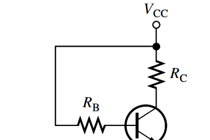
The photodiode is a device that operates in reverse bias, as shown in Figure.

where Ia is the reverse light current. The photodiode has a small transparent window that allows light to strike the pn junction.Photodiode as Variable Resistance Device

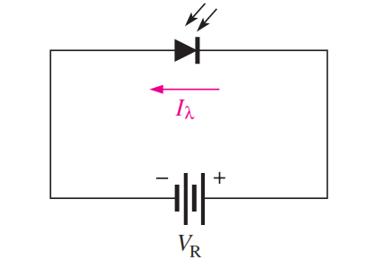
In reverse-biased, a rectifier diode has a very small reverse leakage current. The same is true for a photodiode. The reverse-biased current is produced by thermally generated electron-hole pairs in the depletion region, which are swept across the pn junction by the electric field created by the reverse voltage. In a rectifier diode, the reverse leakage current increases with temperature due to an increase in the number of electron-hole pairs.

A photodiode differs from a rectifier diode in that when its pn junction is exposed to light, the reverse current increases with the light intensity. When there is no incident light, the reverse current, I, is almost negligible and is called the dark current. An increase in the amount of light intensity, expressed as irradiance (mW/cm2), produces an increase in the reverse current, as shown by the graph in Figure (a).

From the graph in Figure (b), you can see that the reverse current for this particular device is approximately 1.4 mA at a reverse-bias voltage of 10 V with an irradiance of 0.5 mW/cm2.

Therefore, the resistance of the device is

photodiode-equation

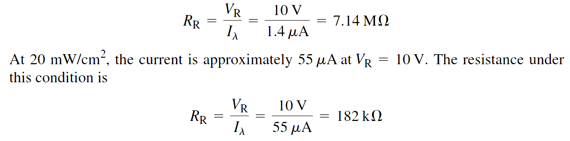
These calculations show that the photodiode can be used as a variable-resistance device controlled by light intensity.

Typical photodiode characteristics

photodiode characteristics

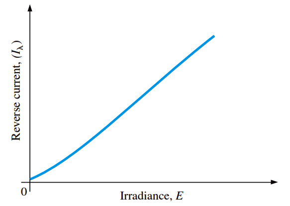
Fig (a) : General graph of reverse current versus irradiance

photodiode-reverse-current-versus-reverse-voltage-for-several

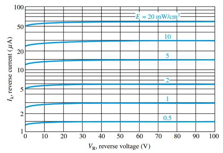
Fig (b) : Example of a graph of reverse current versus reverse voltage for several values of irradiance

Don't Miss Our Updates
Be the first to get exclusive content straight to your email.
We promise not to spam you. You can unsubscribe at any time.
Invalid email address
You've successfully subscribed !

Continue Reading

Full Wave Bridge Rectifier Peak Inverse Voltage
Bridge Rectifier Working Animation
Zener Diode Voltage Regulator Operation
Half Wave Rectifier Principle
Combining Independent Voltage Sources in Series
Half Wave Voltage Doubler using Diodes
Share This Article
Facebook Whatsapp Whatsapp LinkedIn Copy Link
Share
Leave a Comment

Leave a Reply Cancel reply

Your email address will not be published. Required fields are marked *

Stay Connected

128.3kFollowersLike
69.1kFollowersFollow
208kSubscribersSubscribe
38kFollowersFollow

Categories

Explore More

Types of Resistors
Diode Limiters/Clippers Operation
Basics of Ohm’s Law
Shockley Diode Working Principle
Dependent Current Source
CRT Fluorescent Screen
Difference between ideal diode & conventional diode
Voltage Divider Rule
Amplifiers Questions & Answers
Troubleshooting a Biased Transistor

Keep Learning

Center Tapped Full Wave Rectifier Operation

Center Tapped Full Wave Rectifier Operation

Transistor Emitter Feedback Bias

Transistor Emitter Feedback Bias

Reverse Bias Diode Working Animation

Forward Bias & Reverse Bias Diode Working Animation

Diode-vi-characteristic-curve-for-forward-bias

VI Characteristic of a Diode

pi filter Operation

pi filter Operation

photo-diode

Photodiode Working Principle

kirchhoffs-voltage-law

What is Kirchhoff’s Voltage Law

Transistor as an Amplifier in Common Emitter

Transistor as an Amplifier in Common Emitter

Discover More

Center Tap Full-Wave Rectifier

Full-Wave Rectifier Circuit

Control Valve Actuator Parts

Reversing Control Valve Actuator Fail Safe Mode

Vortex Flow Meter Animation

Basic Working Principle of Vortex Flowmeter

Instrumentation and Control (I&C) Design

Instrumentation and Control (I&C) Design

Why Armature is placed on Stator for Synchronous machines

Paddle switch Working Principle

Paddle Switch Working Principle

PLC Program for Temperature Control using Thermostat

PLC Program for Temperature Control using Thermostat

Circuit diagram of Liquid level measurment using Adruino C

Level Measurement and Control using Arduino C

Follow US
All rights reserved. Reproduction in whole or in part without written permission is prohibited.
Welcome Back!

Sign in to your account

Username or Email Address
Password

Lost your password?