Inst ToolsInst ToolsInst Tools
  • Ask
  • Courses
  • Videos
  • Q & A
    • Interview
      • Instrumentation
      • Electronics
      • Electrical
      • Practical Questions
    • MCQ
      • Instrumentation MCQ
      • Electrical MCQ
      • Electronics MCQ
      • Control Systems MCQ
      • Analog Electronics MCQ
      • Digital Electronics MCQ
      • Power Electronics MCQ
      • Microprocessor MCQ
      • Multiple Choice Questions
  • EE
    • Electronics
      • Electronics Q & A
      • Electronic Basics
      • Electronic Devices & Circuits
      • Electronics Animation
      • Digital Electronics
    • Electrical
      • Electrical Basics
      • Electrical Q & A
      • Power Electronics
      • Electrical Machines
      • Electrical Animation
      • Power Systems
      • Switchgear & Protection
      • Transmission & Distribution
  • Measure
    • Control Valves
    • Calibration
    • Temperature
    • Pressure
    • Flow
    • Level
    • Analyzers
    • Switches
    • Vibration
    • Solenoid Valve
  • Control
    • PLC Tutorials
    • Control Systems
    • Safety Instrumented System (SIS)
    • Communication
    • Fire & Gas System
  • More
    • Design
    • Tools
    • Animation
    • Basics
    • Formulas
    • Standards
    • TextBooks
    • Common
    • Software
    • Excel Tools
    • Erection & Commissioning
    • Process Fundamentals
    • Videos
    • Books
Search
All rights reserved. Reproduction in whole or in part without written permission is prohibited.
Reading: Center Tapped Full Wave Rectifier Operation
Share
Notification Show More
Font ResizerAa
Inst ToolsInst Tools
Font ResizerAa
  • Courses
  • PLC Tutorials
  • Control Systems
Search
  • Ask
  • Courses
  • Videos
  • Q & A
    • Interview
    • MCQ
  • EE
    • Electronics
    • Electrical
  • Measure
    • Control Valves
    • Calibration
    • Temperature
    • Pressure
    • Flow
    • Level
    • Analyzers
    • Switches
    • Vibration
    • Solenoid Valve
  • Control
    • PLC Tutorials
    • Control Systems
    • Safety Instrumented System (SIS)
    • Communication
    • Fire & Gas System
  • More
    • Design
    • Tools
    • Animation
    • Basics
    • Formulas
    • Standards
    • TextBooks
    • Common
    • Software
    • Excel Tools
    • Erection & Commissioning
    • Process Fundamentals
    • Videos
    • Books
Follow US
All rights reserved. Reproduction in whole or in part without written permission is prohibited.
Inst Tools > Blog > Electronic Devices & Circuits > Center Tapped Full Wave Rectifier Operation

Center Tapped Full Wave Rectifier Operation

Last updated: October 4, 2016 12:56 pm
Editorial Staff
Electronic Devices & Circuits Electronics Animation
No Comments
Share
1 Min Read
SHARE

A center-tapped rectifier is a type of full-wave rectifier that uses two diodes connected to the secondary of a center-tapped transformer, as shown in Below Figure. The input voltage is coupled through the transformer to the center-tapped secondary. Half of the total secondary voltage appears between the center tap and each end of the secondary winding as shown.

Center Tapped Full Wave Rectifier Operation

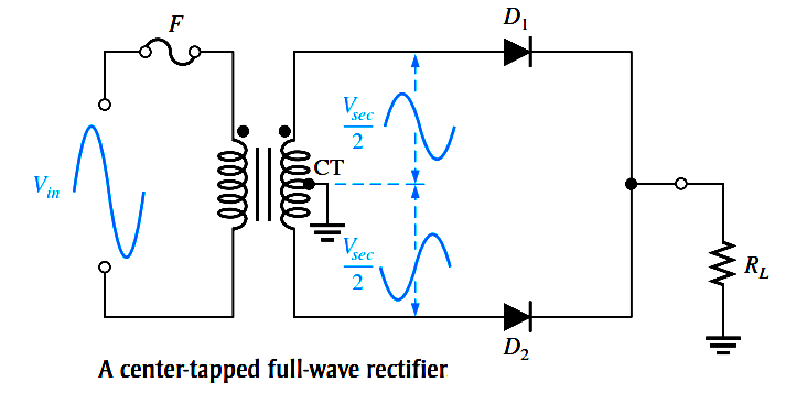
For a positive half-cycle of the input voltage, the polarities of the secondary voltages are as shown in Figure (a). This condition forward-biases diode D1 and reverse-biases diode D2. The current path is through D1 and the load resistor RL, as indicated.

For a negative half-cycle of the input voltage, the voltage polarities on the secondary are as shown in Figure (b). This condition reverse-biases D1 and forward-biases D2. The current path is through D2 and RL, as indicated. Because the output current during both the positive and negative portions of the input cycle is in the same direction through the load, the output voltage developed across the load resistor is a full-wave rectified dc voltage, as shown.

center-tapped-full-wave-rectifier-animation

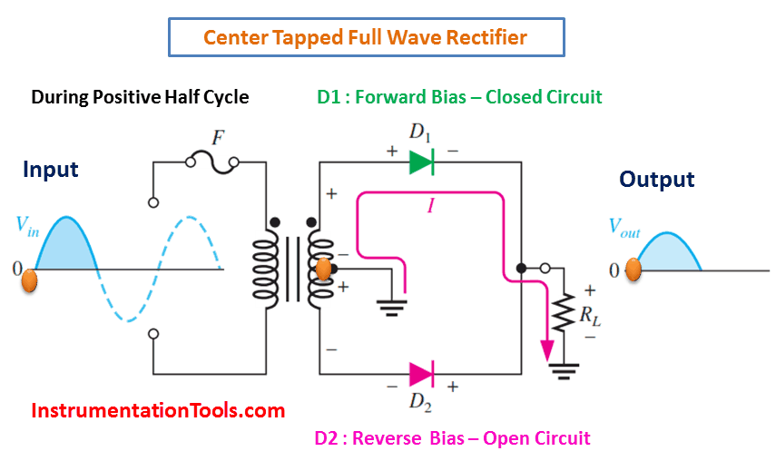
(a) During positive half-cycles, D1 is forward-biased and D2 is reverse-biased.

Center Tapped Full Wave Rectifier Working Animation

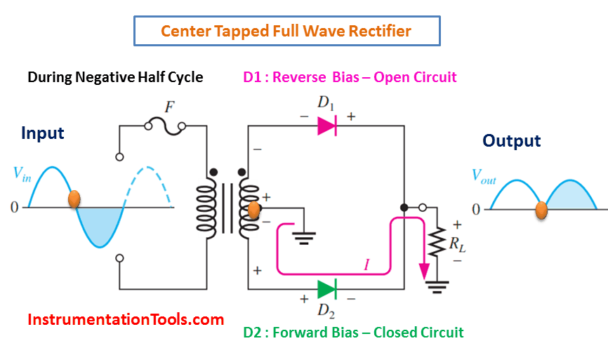
(b) During negative half-cycles, D2 is forward-biased and D1 is reverse-biased.

Don't Miss Our Updates
Be the first to get exclusive content straight to your email.
We promise not to spam you. You can unsubscribe at any time.
Invalid email address
You've successfully subscribed !
Resistors Principle & Applications
Different Types of Diodes
Limitations of Resistors
Cathode Ray Tube (CRT)
Permanent Magnet Moving Coil Instruments (PMMC)
Share This Article
Facebook Whatsapp Whatsapp LinkedIn Copy Link
Share
Leave a Comment

Leave a Reply Cancel reply

Your email address will not be published. Required fields are marked *

Stay Connected

128.3kFollowersLike
69.1kFollowersFollow
208kSubscribersSubscribe
38kFollowersFollow

Categories

Recent Comments

  • Guifty Shimica on Top Non-PLC Certification Courses for Automation Professionals
  • Guifty Shimica on Top Non-PLC Certification Courses for Automation Professionals
  • MIHARITSOA Aina Sitraka on Top Non-PLC Certification Courses for Automation Professionals
  • Vaishnavi on Free Instrumentation Course for Trainee Engineers

Related Articles

basic-electronics-questions-answers

Basic Electronics Questions & Answers

Photodiode as Variable Resistance Device

Photodiode as Variable Resistance Device

Reverse Voltage Characteristics of Photo diode

Characteristics of Photo diode

Zener Diode Limiter Working

Zener Diode Limiter

Transistor as an Amplifier in Common Emitter

Transistor as an Amplifier in Common Emitter

pn-junction-with-depletion-layer

How a PN Junction Formed in a Diode

Capacitor Filter Operation

Capacitor Filter Operation

parallel-resistors-circuit-example

Series and Parallel Resistors

More Articles

Transformers Questions & Answers Part-3

Transformers Questions & Answers Part-3

Parts of Safety PLC

SIS Software Simulation – Safety Instrumented System

Structured Text Automatic Gate Logic

Structured Text PLC Programming for Automatic Gate Control

Types of Calibration

Types of Calibration

Calculate LRV and URV for 4-20 mA Loop-powered DP Transmitter

Calculate LRV and URV for 4-20 mA Loop-powered DP Transmitter

simple motor start-stop circuit

Liquid Level Switch Control Logic

BPCS Control System and ESD Safety System of Delta-V DCS

BPCS Control System and ESD Safety System of Delta-V DCS

PLC Karnaugh maps

How to Simplify PLC Coding Using Karnaugh Maps?

Follow US
All rights reserved. Reproduction in whole or in part without written permission is prohibited.
Welcome Back!

Sign in to your account

Username or Email Address
Password

Lost your password?