Inst ToolsInst ToolsInst Tools
  • Ask
  • Courses
  • Videos
  • Q & A
    • Interview
      • Instrumentation
      • Electronics
      • Electrical
      • Practical Questions
    • MCQ
      • Instrumentation MCQ
      • Electrical MCQ
      • Electronics MCQ
      • Control Systems MCQ
      • Analog Electronics MCQ
      • Digital Electronics MCQ
      • Power Electronics MCQ
      • Microprocessor MCQ
      • Multiple Choice Questions
  • EE
    • Electronics
      • Electronics Q & A
      • Electronic Basics
      • Electronic Devices & Circuits
      • Electronics Animation
      • Digital Electronics
    • Electrical
      • Electrical Basics
      • Electrical Q & A
      • Power Electronics
      • Electrical Machines
      • Electrical Animation
      • Power Systems
      • Switchgear & Protection
      • Transmission & Distribution
  • Measure
    • Control Valves
    • Calibration
    • Temperature
    • Pressure
    • Flow
    • Level
    • Analyzers
    • Switches
    • Vibration
    • Solenoid Valve
  • Control
    • PLC Tutorials
    • Control Systems
    • Safety Instrumented System (SIS)
    • Communication
    • Fire & Gas System
  • More
    • Design
    • Tools
    • Animation
    • Basics
    • Formulas
    • Standards
    • TextBooks
    • Common
    • Software
    • Excel Tools
    • Erection & Commissioning
    • Process Fundamentals
    • Videos
    • Books
Search
All rights reserved. Reproduction in whole or in part without written permission is prohibited.
Reading: Zener Diode Voltage Regulator Operation
Share
Notification Show More
Font ResizerAa
Inst ToolsInst Tools
Font ResizerAa
  • Courses
  • PLC Tutorials
  • Control Systems
Search
  • Ask
  • Courses
  • Videos
  • Q & A
    • Interview
    • MCQ
  • EE
    • Electronics
    • Electrical
  • Measure
    • Control Valves
    • Calibration
    • Temperature
    • Pressure
    • Flow
    • Level
    • Analyzers
    • Switches
    • Vibration
    • Solenoid Valve
  • Control
    • PLC Tutorials
    • Control Systems
    • Safety Instrumented System (SIS)
    • Communication
    • Fire & Gas System
  • More
    • Design
    • Tools
    • Animation
    • Basics
    • Formulas
    • Standards
    • TextBooks
    • Common
    • Software
    • Excel Tools
    • Erection & Commissioning
    • Process Fundamentals
    • Videos
    • Books
Follow US
All rights reserved. Reproduction in whole or in part without written permission is prohibited.
Inst Tools > Blog > Electronic Devices & Circuits > Zener Diode Voltage Regulator Operation

Zener Diode Voltage Regulator Operation

Last updated: November 17, 2017 9:05 am
Editorial Staff
Electronic Devices & Circuits
No Comments
Share
3 Min Read
SHARE

The zener diode can be used as a type of voltage regulator for providing stable reference voltages. In this section, you will see how zeners can be used as voltage references, regulators, and as simple limiters or clippers.

Zener Regulation with a Variable Input Voltage

Zener diode regulators can provide a reasonably constant dc level at the output, but they are not particularly efficient. For this reason, they are limited to applications that require only low current to the load. The Below Figure illustrates how a zener diode can be used to regulate a dc voltage. As the input voltage varies (within limits), the zener diode maintains a nearly constant output voltage across its terminals.

However, as VIN changes, IZ will change proportionally so that the limitations on the input voltage variation are set by the minimum and maximum current values (IZK and IZM) with which the zener can operate. Resistor R is the series current-limiting resistor. The meters indicate the relative values and trends.

Zener Diode Voltage Regulator Operation

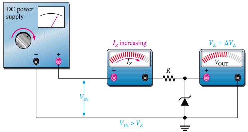
Fig (a) : As the input voltage increases, the output voltage remains nearly constant (IZK < IZ < IZM).

Zener Diode Voltage Regulator

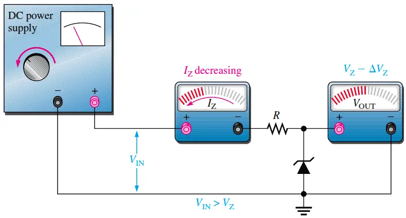
Fig (b) : As the input voltage decreases, the output voltage remains nearly constant (IZK < IZ < IZM).

Example :

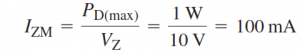
To illustrate regulation, let’s use the ideal model of the 1N4740A zener diode (ignoring the zener resistance) in the circuit shown below. The absolute lowest current that will maintain regulation is specified at Izk which for the 1N4740A is 0.25 mA and represents the no-load current. The maximum current is not given on the datasheet but can be calculated from the power specification of 1 W, which is given on the datasheet. Keep in mind that both the minimum and maximum values are at the operating extremes and represent worst-case operation.

Zener Diode Circuit

Zener Diode Circuit Formula

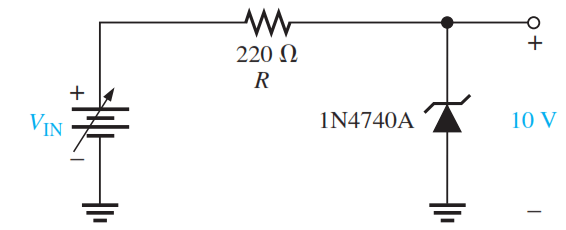
For the minimum zener current, the voltage across the 220 ohms resistor is

Vr = Izk.R = (0.25 mA)(220 ohms) = 55 mV

Since VR = VIN – VZ,

Vin(min) = VR + VZ = 55 mV + 10 V = 10.055 V

For the maximum zener current, the voltage across the 220 ohms resistor is

VR = IzmR = (100 mA)(220 ohms) = 22 V

Therefore,

VIN(max) = 22 V + 10 V = 32 V

This shows that this zener diode can ideally regulate an input voltage from 10.055 V to 32 V and maintain an approximate 10 V output. The output will vary slightly because of the zener impedance, which has been neglected in these calculations.

Don't Miss Our Updates
Be the first to get exclusive content straight to your email.
We promise not to spam you. You can unsubscribe at any time.
Invalid email address
You've successfully subscribed !
Transistors Questions & Answers
Cathode Ray Tube Deflection System
Comparison of MOSFET and BJT
Transistor Base Bias
Capacitor Filter Operation
Share This Article
Facebook Whatsapp Whatsapp LinkedIn Copy Link
Share
Leave a Comment

Leave a Reply Cancel reply

Your email address will not be published. Required fields are marked *

Stay Connected

128.3kFollowersLike
69.1kFollowersFollow
208kSubscribersSubscribe
38kFollowersFollow

Categories

Recent Comments

  • Guifty Shimica on Top Non-PLC Certification Courses for Automation Professionals
  • Guifty Shimica on Top Non-PLC Certification Courses for Automation Professionals
  • MIHARITSOA Aina Sitraka on Top Non-PLC Certification Courses for Automation Professionals
  • Vaishnavi on Free Instrumentation Course for Trainee Engineers

Related Articles

Diode-vi-characteristic-curve-for-forward-bias

VI Characteristic of a Diode

Shockley Diode Working Principle

Shockley Diode Working Principle

Derivation-of-Ohms-Law

Basics of Ohm’s Law

Basics of Amplifiers Interview Questions

Amplifiers Questions & Answers

phototransistor-circuit

Phototransistor Circuit Example

capacitor-filter

Capacitor Filter Working Principle

half-wave-voltage-doubler-using-diodes

Half Wave Voltage Doubler using Diodes

Voltage Divider Rule

Voltage Divider Rule

More Articles

What is an ELV System - Extra Low Voltage

What is an ELV System? – Extra Low Voltage

Current Earth Leakage Circuit Breaker

Types of Earth Leakage Circuit Breaker

PLC Programming for Sequential Batch Mixing System

PLC Programming for Sequential Batch Mixing System

Oscillating Piston Flow Meters Principle Animation

Nutating Disc Flow Meters Working Principle

Square root extractor Parts

What is a Square Root Extractor? – DP Flow Measurement

Calculate Power in Parallel RCL Circuit

Calculate Power in Parallel RCL Circuit

SMART Transmitters Block Diagram

Smart Transmitters LRV & URV

feed flow transmitter

Flowmeter Control Strategy

Follow US
All rights reserved. Reproduction in whole or in part without written permission is prohibited.
Welcome Back!

Sign in to your account

Username or Email Address
Password

Lost your password?