The Bourdon pressure gauge uses the principle that a flattened tube tends to straighten or regain its circular form in cross-section when pressurized.
Although this change in cross-section may be hardly noticeable, and thus involving moderate stresses within the elastic range of easily workable materials, the strain of the material of the tube is magnified by forming the tube into a C shape or even a helix, such that the entire tube tends to straighten out or uncoil, elastically, as it is pressurized.
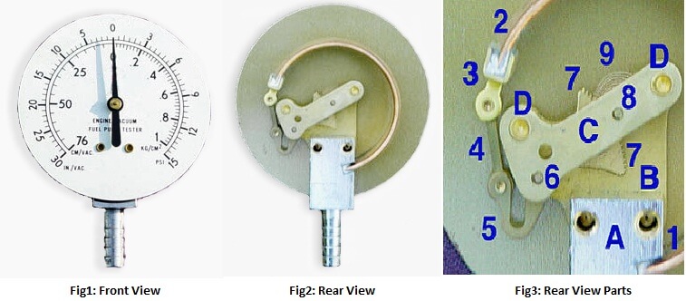
In practice, a flattened thin-wall, closed-end tube is connected at the hollow end to a fixed pipe containing the fluid pressure to be measured. As the pressure increases, the closed end moves in an arc, and this motion is converted into the rotation of a (segment of a) gear by a connecting link that is usually adjustable.
A small-diameter pinion gear is on the pointer shaft, so the motion is magnified further by the gear ratio. The positioning of the indicator card behind the pointer, the initial pointer shaft position, the linkage length and initial position, all provide means to calibrate the pointer to indicate the desired range of pressure for variations in the behavior of the Bourdon tube itself.
Differential pressure can be measured by gauges containing two different Bourdon tubes, with connecting linkages.
Stationary parts:
Moving Parts:
Also Read: Working Principle of Rotameters
Learn an example PLC program to control a pump based on level sensors using ladder…
In the PLC timer application for security camera recording, when motion is detected then camera…
In this example, we will learn batch mixing with PLC ladder logic program using timer…
This PLC example on manufacturing line assembly is an intermediate-level PLC program prepared for the…
In this article, you will learn the PLC programming example with pushbutton and motor control…
This article teaches how to convert Boolean logic to PLC programming ladder logic with the…


View Comments
I WANT MORE DIAGRAMITIC RESPRESSENTION AND SPECIFIC WORKING PRINCIPLES IN DETAIL OF A PRESSURE GAUGE