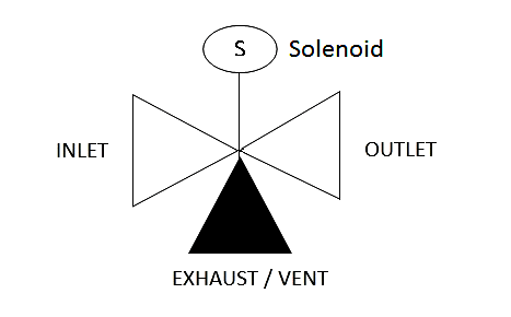
Solenoid valves are often used in some applications in which a control valve under certain conditions requires where it quickly was driven to the fail position.
Solenoid valves are usually electrically actuated on-off or three-way valves installed into the air system and designed to take a specific action when tripped.

The solenoid can be thought of as an on-off switch for a pneumatic system.
The signal to the solenoid controls the action of the internal valve assembly, allowing flow through the valve in one position and in other position isolating or venting the air.
For example, there is a control valve which requires quick action in the fail-safe condition in emergency situations, then a 2 way SOV is installed between Positioner output and Actuator inlet.
When the SOV is energized condition then SOV inlet connected to the outlet and allowing air to flow from Positioner output to the actuator.
When SOV is in de-energized condition then output is connected with vent (Exhaust port) and its venting the control valve air from exhaust port quickly and moving the valve to the fail-safe position.
In some cases, it has been found out that due to SOV failure (SOV may fail due to many reasons like Coil open, fuse blown, Plunger stuck up, passing in SOV, etc) control valve goes to fail-safe condition and its leads to trip the plant due to closing /opening the valve or may cause some unwanted process disturbances.
As the shutdown of the plant goes very expensive, so dual SOV philosophy comes for redundancy purposes.
In dual SOV, if one SOV fails then the plant will not disturb.
Dual SOV pneumatic schematic shows in the below Figure.
Suppose that Air continuously going to the actuator in normal condition.
Positioner output is connected in both SOV inlet, SOV-1 outlet is connected to SOV-2 exhaust and final output goes from SOV-2 to the actuator.
If SOV-1 is going failure then the SOV-1 output port is connected with exhaust and air is going from SOV-2 because SOV-2 is energized and the inlet is connected to the output.
Air Flow indications are shown in the above figure with the arrows.
If SOV-2 becomes failure then the SOV-2 outlet is connected with exhaust and SOV-1 is energized then the air goes from SOV-1 inlet to outlet then outlet is connected with SOV-2 exhaust which is connected with SOV-2 outlet in fail condition and the air is going to actuator.
Air Flow indications are shown in the above figure with the arrows.
When both SOV is de energies then both SOV outlet is connected with exhaust and block the inlet then actuator air is released from SOV-2 outlet to exhaust then exhaust is connected with SOV-1 outlet and SOV-1 outlet connected with exhaust and air is released.
Air Flow indications are shown in the above figure with the arrows.
Check the monthly surface temperature of SOV by the pyrometer. if both SOVs are from the same company then the surface temperature is almost equal. (Max difference between both SOV is 5 deg c). If the temperature difference is more then check the coil resistance.
Check physically the exhaust port that air is blocked or in normal condition.
Sponsored: Solenoid-valve.world
Author: Ashish Agrawal
The PLC panel and MCC panel interface signals are start, stop, run feedback, trip, local…
In this article, we are going to discuss about shutter door control using induction motor…
Electrical Drives control the motion of electric motors. Motion control is required in industrial and…
PLC ladder logic design to control 3 motors with toggle switch and explain the program…
VFD simulator download: Master the online tool from the Yaskawa V1000 & programming software for…
The conveyor sorting machine is widely used in the packing industries using the PLC program…
View Comments
no any data about absolute presure transmitters and gauges???
Please check in "Pressure Measurement" category
What is the ordinary value of thd sov coil that should be found when checking ?
Depends on sov, please look at the resp. data-sheet. Usually the power is shown.
please show dry calibration calculation for single and interface level troll
A great and useful study centre of instrumentation field...i really appreciate that to its honour.
In this article both sovs are de energised due to problem & you tell air was released from actuator &inlet air blocked
But in that time my control valve do not close that means not to disturb the valve
What we will do?
Go to another sov...?