Inst ToolsInst ToolsInst Tools
  • Courses
  • Automation
    • PLC
    • Control System
    • Safety System
    • Communication
    • Fire & Gas System
  • Instrumentation
    • Design
    • Pressure
    • Temperature
    • Flow
    • Level
    • Vibration
    • Analyzer
    • Control Valve
    • Switch
    • Calibration
    • Erection & Commissioning
  • Interview
    • Instrumentation
    • Electrical
    • Electronics
    • Practical
  • Q&A
    • Instrumentation
    • Control System
    • Electrical
    • Electronics
    • Analog Electronics
    • Digital Electronics
    • Power Electronics
    • Microprocessor
Search
  • Books
  • Software
  • Projects
  • Process
  • Tools
  • Basics
  • Formula
  • Power Plant
  • Root Cause Analysis
  • Electrical Basics
  • Animation
  • Standards
  • 4-20 mA Course
  • Siemens PLC Course
Reading: Why Bias used in Proportional Controller ?
Share
Notification Show More
Font ResizerAa
Inst ToolsInst Tools
Font ResizerAa
  • Courses
  • Design
  • PLC
  • Interview
  • Control System
Search
  • Courses
  • Automation
    • PLC
    • Control System
    • Safety System
    • Communication
    • Fire & Gas System
  • Instrumentation
    • Design
    • Pressure
    • Temperature
    • Flow
    • Level
    • Vibration
    • Analyzer
    • Control Valve
    • Switch
    • Calibration
    • Erection & Commissioning
  • Interview
    • Instrumentation
    • Electrical
    • Electronics
    • Practical
  • Q&A
    • Instrumentation
    • Control System
    • Electrical
    • Electronics
    • Analog Electronics
    • Digital Electronics
    • Power Electronics
    • Microprocessor
Follow US
All rights reserved. Reproduction in whole or in part without written permission is prohibited.
Inst Tools > Blog > Control Systems > Why Bias used in Proportional Controller ?

Why Bias used in Proportional Controller ?

Last updated: March 18, 2019 2:29 pm
Editorial Staff
Control Systems
No Comments
Share
3 Min Read
SHARE

The P-Only Algorithm

Contents
Understanding Controller BiasController Gain, Kc

The P-Only controller computes a CO action every loop sample time T as:

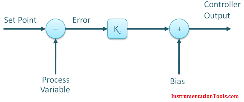
  CO = CObias + Kc∙e(t)

Where:
CObias = controller bias or null value
Kc = controller gain, a tuning parameter
e(t) = controller error = SP – PV
SP = set point
PV = process variable

Understanding Controller Bias

Let’s suppose the P-Only control algorithm shown above is used for speed control in an automobile and CO is the throttle signal adjusting the flow of fuel to the engine.

Let’s also suppose that the speed SP is 70 and the measured PV is also 70 (units can be mph or kph ). Since PV = SP, then e(t) = 0 and the algorithm reduces to:

  CO = CObias + Kc∙(0) = CObiasBias in Proportional Controller

If CObias is zero, then when set point equals measurement, the above equation says that the throttle signal, CO, is also zero. This makes no sense. Clearly if the car is traveling 70 kph, then some baseline flow of fuel is going to the engine.

This baseline value of the CO is called the bias or null value. In this example, CObias is the flow of fuel that, in manual mode, causes the car to travel the set speed of 70 kph.

A P-Only controller bias (sometimes called null value) is assigned a value as part of the controller design and remains fixed once the controller is put in automatic.

Controller Gain, Kc

The P-Only controller has the advantage of having only one adjustable or tuning parameter, Kc, that defines how active or aggressive the CO will move in response to changes in controller error, e(t).

For a given value of e(t) in the P-Only algorithm above, if Kc is small, then the amount added to CObias is small and the controller response will be slow or sluggish. If Kc is large, then the amount added to CObias is large and the controller response will be fast or aggressive.

Thus, Kc can be adjusted or tuned for each process to make the controller more or less active in its actions when measurement does not equal set point.

Also Read: Why Offset in Proportional Controller ?

Don't Miss Our Updates
Be the first to get exclusive content straight to your email.
We promise not to spam you. You can unsubscribe at any time.
Invalid email address
You've successfully subscribed !

Continue Reading

Difference between Router, Switch, and Hub
Proportional-only Offset
Limit, Selector, and Override controls
Proportional Controller Principle
Difference between Fieldbus, Profibus and HART Protocols
SCADA Systems
Share This Article
Facebook Whatsapp Whatsapp LinkedIn Copy Link
Share
Leave a Comment

Leave a Reply Cancel reply

Your email address will not be published. Required fields are marked *

Stay Connected

128.3kFollowersLike
69.1kFollowersFollow
210kSubscribersSubscribe
38kFollowersFollow

Categories

Explore More

PLC Alarm and Trip Documentation
Ziegler-Nichols Closed-Loop Method (Ultimate Gain)
What is Marshalling Cabinet?
Add On Instructions Programming – Analog Input Devices in Studio 5000
Integrating Processes – Liquid Level Control
What is Instrumentation and Control ?
Background of Modbus – ASCII and RTU Data Frames
4-wire Passive versus Active Transmitters

Keep Learning

Top 5 Advantages of Human-Machine Interface (HMI)

Top 5 Advantages of Human-Machine Interface (HMI)

Basic Control Systems Questions

14 Basic Control Systems Questions for Interview Preparation

Pressure and Level Control Loop

Problem on Pressure and Level Control Loops

Electrical Circuit Label Schematic

Label the Electrical Circuit Schematic

Process Control Automation PLC Quiz

Process Control Automation PLC Quiz

Controller Output Current Loop

DCS Controllers to Output Current Loops

How to Implement Ratio Control in this System

How to Implement Ratio Control in this System?

Process Shutdown

Difference between Process shutdown and Emergency Shutdown

Learn More

DP-Transmitter-with-two-seals

DP Transmitter with Two Seals applications

Technologies for Oxygen Gas Measurement

Technologies for Oxygen Gas Measurement

5-Port-2-Position-Valve-Animation

5 Port 2 Position Valve Working Principle

schottky diode working principle

Schottky Diode Working Principle

magnetic-level-gauge-principle

Magnetic Level Gauge Working Principle Animation

Quantitative PID tuning procedures

Quantitative PID tuning procedures

Pneumatic Actuators Types Animation

Types of Pneumatic Actuators Animation

What is Fuzzy Logic

What is Fuzzy Logic? Advantages, Disadvantages, Applications

Menu

  • About
  • Privacy Policy
  • Copyright

Quick Links

  • Learn PLC
  • Helping Hand
  • Part Time Job

YouTube Subscribe

Follow US
All rights reserved. Reproduction in whole or in part without written permission is prohibited.
Welcome Back!

Sign in to your account

Username or Email Address
Password

Lost your password?