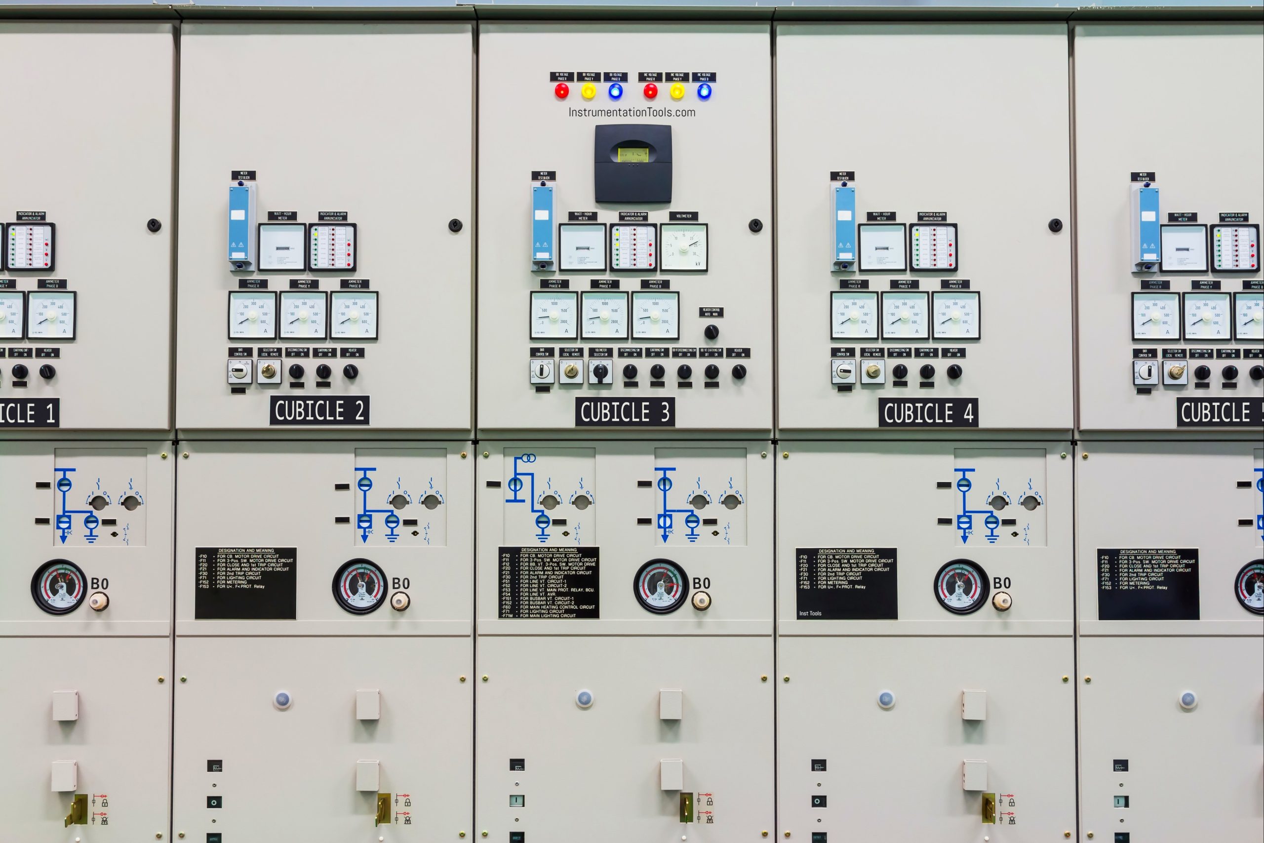
Switchgear
The system used for switching, controlling, isolating, and protecting the electrical circuits and equipment is known as Switchgear.
Switchgear is a part of the substation. Switchgear in substations are located on both sides of high voltage, low voltage sides of large transformers units.
The Switchgear carries out the functions of carrying, making, and breaking the normal load current like a switch.
It will execute the functions of clearing the fault current for which sensing devices like current transformers (CT), Potential transformer (PT), and various types of relays depending upon the application are involved.
Switchgear in a power plant is a place where various switching, measuring, and protective equipment are located and their work is to make or isolate various electrical auxiliaries i.e. electrical machines which feed power to various plant auxiliaries like boiler feed water, condensate pumps, seal oil pumps, etc.
Components of Switchgear
Switchgear is not a single object, predominantly consists of switching and protecting devices such as
- Switches,
- Fuses,
- Isolators,
- Circuit breakers,
- Protective relays,
- Current transformers,
- Potential transformers
- Conductors
and various associated equipment.
Classification of Switchgear
The switchgear can be classified into three categories:
- Low voltage switchgear
- Medium voltage switchgear
- High voltage switchgear
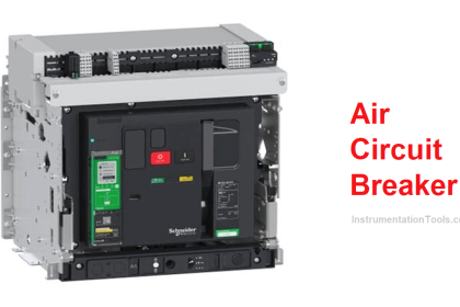
Low voltage Switchgear: low voltage switchgear range from 1000 V to 1500 Volts.
These include Air Circuit breakers, HRC fuses, ELCB, RCCB, Isolators.
Medium Voltage Switchgear: Medium Voltage switchgear range from 3.3 Kilo Volts to 33 Kilo Volts.
Oil Circuit breakers (minimum oil and bulk oil circuit breakers), Vacuum Circuit breakers.
High voltage Switchgear: High voltage circuit breakers range from 36 Kilo Volts and above. SF6 circuit breakers.

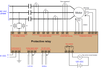
Current Transformers: The primary circuit currents which are of high magnitude are to be reduced to values suitable for relay operation with the help of current transformers (CTs).
The primary winding of the CT is connected in series with the load and carries the actual power system currents it may be normal or fault.
Voltage Transformers: It is not possible to connect the voltage coils of the protective devices directly to the system in the case of high voltage systems.
Hence it is necessary to step down the voltage and also to insulate the protective equipment from the primary power circuit.
This is achieved by using a voltage transformer (VT) also known also a potential transformer (PT).
Substation
The substation provides interconnection of transmission circuits and distribution systems and various voltage levels.
The substation is connected to the electrical network through an overhead line.
Classification of Substation
Substations are classified into two Air Insulated Substation (AIS), and Gas Insulated Substation (GIS).
Air Insulated Substation (AIS)
In the case of AIS, open terminal arrangement utilizes primary equipment whose terminals are in the air.
Consequently, large clearances are required between these terminals and earth, between terminals of different phases.
This kind of substations occupies a large quantity of land. Most of the substations are AIS only.
Gas Insulated Substation (GIS)
In the case of GIS, utilizes Sulphur Hexafluoride (SF6) gas to allow the phase to phase and phase to earth clearance drastically.
This kind of substations is used in cities, where land cost is very expensive.
Components of Substation
A substation generally comprise
- Switchgear
- Power transformers
- Bus bars
- Protection, control, and monitoring equipment
- Substation lighting protective system
- Substation earth System
- Lightning arrestors
Substation comprises three components
- Primary system.
- Secondary system
- Auxiliary supply stem
Primary system: It comprises all equipment that is in service at the supposed nominal voltage system.
Secondary System: It comprises all equipment that is used for the control, protection, measurement, and monitoring equipment.
Auxiliary Supply System: An auxiliary supply system comprises all equipment such as Air conditioning, DC supplies that enable protection, control, measurement, and monitoring equipment to operate.
Types of Substation
- Transmission Substation,
- Distribution Substation.
Transmission Substation
The power is generated at generating station, a substation is used in-house to generating stations to step up the voltage level for transmission.
If the voltage level is further to be increased for long-distance transmission then another substation is employed for stepping up the voltage.
Distribution Substation
Again, the power which is transmitted at very high voltage is not suitable for the consumer end (domestic or industrial) and there the distribution substation comes into the picture.
It steps down the voltage to a level that is suitable for distribution, say 440 V, 3.3 kV, 6.6 kV, and 11 kV depending upon the type of consumer.
The consumer may be domestic or industrial.
Substation Layout Preparation
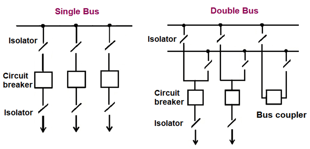
The small substations, where continuity of the supply to consumers is not critical or not essential uses the single bus system. It is simple and economical.
But in large substations, the additional bus bar (double bus bar) is used in the system so that the interruption does not occur in their supply.
If you liked this article, then please subscribe to our YouTube Channel for Instrumentation, Electrical, PLC, and SCADA video tutorials.
You can also follow us on Facebook and Twitter to receive daily updates.
Read Next:
- Compare Soft Starter and VFD
- Download Electrical Enclosure Book
- Instantaneous Trip Circuit Breaker
- What is an Electrical Drive?
- Interview Questions on Transformer


THANKS A MILLION. YOUR EXPLAINATION ON SWITCHGEAR AND ELECTRICAL SUBSTATION WAS SIMPLE, CONCISE AND TO THE POINT. THIS MAKE LEARNING VERY EASY AND INTERESTING.
THANKS.
HISSIN
Can you please provides a chart flow diaghram of Low, medium and high voltage , substation to overhead line. Flow line of switchgear & transformer.