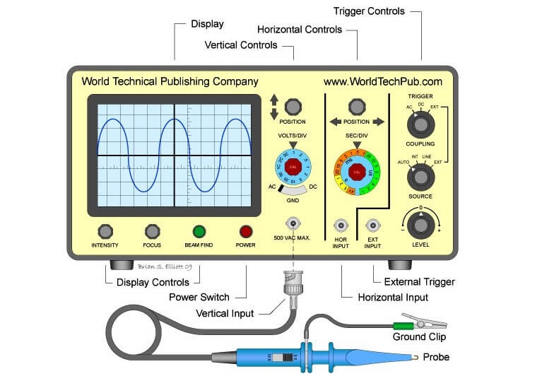
In studying the various electronic, electrical networks and systems, signals which are functions of time, are often encountered. Such signals may be periodic or non-periodic in nature. The device which allows, the amplitude of such signals, to be displayed primarily as a function of time is called cathode ray oscilloscope, commonly known as CRO. The C.R.O gives the Visual representation of the time varying signals. The oscilloscope has become an universal instrument and is probably most versatile tool for the development of electronic circuits and systems. It is an integral part of electronic laboratories.

The oscilloscope is, in fact, a voltmeter. Yes, you read it right. It is in fact, a voltmeter. Instead of the mechanical deflection of a metallic pointer as used in the normal voltmeters, the oscilloscope uses the movement of a visible spot. The movement of such spot on the screen is proportional to the varying magnitude of the signal, which is under measurement.
The electron beam can be deflected in two directions: the horizontal or x-direction and the vertical or y-direction. Thus an electron beam producing a spot can be used to produce two dimensional displays. Thus C.R.O can be regarded as a fast x-y plotter. The x-axis and y-axis can be used study the variation of one voltage as a function of another.
Typically the x-axis of the oscilloscope represents the time while the y-axis represents variation of the input voltage signal. Thus if the input voltage signal applied to the y-axis of C.R.O is sinusoidally varying and if x-axis represents the time axis, then the spot moves sinusoidally, and the familiar sinusoidal waveform can be seen on the screen of the oscilloscope. The oscilloscope is so fast device that it can display the periodic signals whose time period is as small as microseconds and even nanoseconds. The C.R.O basically operates on voltages, but it is possible to convert current, pressure, strain, acceleration and other physical quantities into the voltage using transducers and obtain their visual representations on the C.R.O.
This article explains how to blink lights in ladder logic with a detailed explanation video…
In this article, a simple example will teach you the conversion from Boolean algebra to…
In this article, you will learn the PLC cooking timer example for kitchen automation using…
Learn an example PLC program to control a pump based on level sensors using ladder…
In the PLC timer application for security camera recording, when motion is detected then camera…
In this example, we will learn batch mixing with PLC ladder logic program using timer…