Differential pressure meters work on the principle of partially obstructing the flow in a pipe. This creates a difference in the static pressure between the upstream and downstream sides of the device.
This difference in the static pressure (referred to as the differential pressure) is measured and used to determine the flow rate.
Differential-pressure meters are hugely popular and it is estimated that at least 40% of industrial flow meters in use at present are differential-pressure devices, with the orifice plate being the most popular. Differential-pressure devices have been used to meter a wide variety of different fluids from gases to highly viscous liquids.
The popularity of differential-pressure flow meters is in part due to their simple design and low cost. By reading this guide you will have a much clearer idea of the benefits, viable metering options, and applications for using differential-pressure meters.
The concept of using the pressure drop caused by a fluid flowing through a restriction in a pipe as a measurement of flow rate dates back to the 18th Century, when it was discovered by Bernoulli.
The basic principle of how a Δp flow meter operates is described in the figure below.
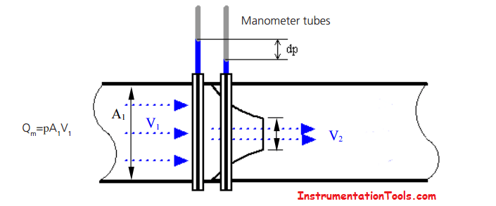
The differential pressure principle. Manometer tubes measure the difference in static pressure upstream and downstream of the restriction
When a fluid flows through a restriction, it accelerates to a higher velocity (i.e. V2 > V1 ) to conserve the mass flow, and, as a consequence of this, its static pressure drops. This differential pressure (Δp) is then a measure of the flow rate through the device.
In simple terms for a given size of restriction, the higher the Δp, the higher the flow rate.
The relationship between the differential pressure and flow rate is derived from Bernoulli’s equation.
Using Bernoulli’s equation, and conservation of mass, it can be shown that the differential pressure generated is proportional to the square of the mass flow rate, Qm (kg/s)
Many of the Δp meters available work on this principle of measuring the difference in pressure between upstream and downstream but there are some meters that use the differential pressure in other ways, for example, variable area meters.
The most common types of differential pressure meter are:
There are a number of general advantages common to most DP meters.
These include:
The main disadvantages of DP meters are:
Common Terminology
The diameter ratio or beta (sometimes referred to as the beta ratio) is the ratio between the diameter of the orifice or throat of the device to that of the pipe.
Often Δp meters are described in terms of their beta value and diameter to fit a certain pipeline size, for example, a 4-inch β= 0.6 Venturi tube.
To state that a Δp meter has a low beta ratio, for example, β = 0.2, means the plate has a small hole or restriction size.
This causes the pressure loss across the Δp meter to be higher, which may mean that a pump with a higher discharge pressure (hence more expensive) or compressor will be needed to overcome the increased pressure loss and maintain a flow rate achievable with a larger beta Δp meter.
On the other hand, a higher differential pressure can generally be measured more accurately than a lower one.
The effects of using larger values of beta include:
There are a number of sizing packages for orifice plates available, which will calculate the dimensions of the plate required. The software uses empirical formulae based on actual testing. Most of the results are available for beta values of 0.3 to 0.7.
The discharge coefficient, C, is a parameter that takes account of non-ideal effects, for example, energy losses due to friction, when using Δp meters.
The discharge coefficient is basically the ratio of the actual to the measured mass flow rate.
The discharge coefficient can either be:
1. determined from a standard
or
2. determined by calibration
In nozzles and Venturi tubes the flow follows the boundary of the tube closely and the value of C is usually close to one.
However, for orifice plates C has a value of approximately 0.6. Values of C can be obtained from the standard (ISO 5167) for nozzles, Venturi tubes and orifice plates that are manufactured to the specified tolerances of the standard.
The turndown of a meter is the ratio of the maximum to the minimum flowrate that can be accurately measured. Ideally a large a turndown ratio is desirable to measure a wide range of flowrates
Square relationship between flowrate and Δp:
The following graph illustrates the square relationship between the differential pressure and the flowrate.
This shows that a turndown of 10:1 on flowrate will require a 100:1 turndown on pressure measurement (this is provided the density is approximately constant e.g. for a liquid).
As it is very difficult to obtain accurate measurements over such a large range of Δp values from a simple transmitter, this means that the typical turndown of a Δp meter is actually limited to approximately 4:1 to obtain an accurate measurement of flowrate.
At low values of the flowrate the Δp transmitter uncertainty increases significantly. For example, a Δp cell can typically offer an uncertainty of 0.2% of Full Scale (FS). This means that, at 1% FS, the uncertainty of the differential pressure would be 20%. Therefore at low flowrates it becomes much more difficult to measure the Δp.
The turndown of the meter can be extended to around 10:1 if multiple range transducers are used. For example, one Δp transducer could be ranged for 1 – 10% FS and another over the range of 10 – 100% FS.
Once a value for the Δp has been obtained, the mass flow can be calculated using the following formula.
For liquids the mass flow is given by:
Where:
C is the discharge coefficient
At is the throat area (restriction)
Δp is the differential pressure
p is the density of the fluid
d is the diameter of the throat
D is the pipe diameter
Owing to the compressibility of gases an additional parameter called the expansibility factor, ε, is used within the mass flow equation to account for the gas density changing as the pressure drops at the restriction.
For gases the mass flow is given by:
If you liked this article, then please subscribe to our YouTube Channel for Instrumentation, Electrical, PLC, and SCADA video tutorials.
You can also follow us on Facebook and Twitter to receive daily updates.
Read Next:
In this example, we will learn batch mixing with PLC ladder logic program using timer…
This PLC example on manufacturing line assembly is an intermediate-level PLC program prepared for the…
In this article, you will learn the PLC programming example with pushbutton and motor control…
This article teaches how to convert Boolean logic to PLC programming ladder logic with the…
In this article, you will learn the PLC programming example on timers function block using…
Design a program for PLC pump control such that the pump must be turned ON…


View Comments
thank a lot sir, your website is very good for instrument and control job, sir...can you fill up article step by step commissioning for calibration control valve like fisher or neles metso, thanks
Thank You.................
Dear sir
Thanks for helping us.
Please help me how we can get mass flow rate of gases based on differential pressure measurement with orifice plate after temperature and pressure compensation. Please explain and give equation.
Dear Sir
your explanation is quite good and thanks a lot for that.
But can you explain how to determine expansibility factor.
I will be very grateful to you for this.
Regards
Dear Sir,
I’m looking flow meter system with online. We will use it in textile spinning industries where we will control our flow with mobile app or computer. Please send us quotation of 10 meters with complete system.
We are looking your quick and kind response.
Feel free and contact us for any further details