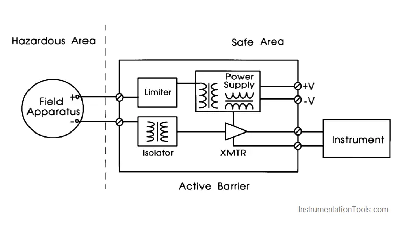
An active barrier uses transformers, optoisolators or relays to provide isolation between the hazardous area and the non-hazardous area.
It does not require an intrinsically safe ground connection. Either or both the hazardous area or the non-hazardous area signals may be grounded.
This may be the most logical barrier choice if a high quality I.S. grounding point is not available.
The below Figure shows a diagram of an active barrier. The barrier requires a 24 VDC power supply, and can typically drive larger loads than a loop powered zener barrier.
Active Barrier
Intrinsically safe systems should satisfy these requirements:
- Ensure that there is a positive separation of intrinsically safe and non-intrinsically safe circuits. This prevents the ignition capable energy from intruding into the intrinsically safe circuit.
- Separate conduit, panduit, cable trays, etc. should be used for I.S. wiring to keep it separate from the non-I.S. wiring. If conduit is used, it must be sealed per the applicable code. This is to prevent the conduit from becoming a means of conducting flammable material from the hazardous to the non-hazardous location. I.S. wiring must always be identified. This can be performed by tagging the wires, labelling the junction boxes, and/or color-coding the I.S. wires light blue.
- Ensure that the entity parameters, upon which approval of the system is based, match up correctly.
