Inst ToolsInst ToolsInst Tools
  • Courses
  • Automation
    • PLC
    • Control System
    • Safety System
    • Communication
    • Fire & Gas System
  • Instrumentation
    • Design
    • Pressure
    • Temperature
    • Flow
    • Level
    • Vibration
    • Analyzer
    • Control Valve
    • Switch
    • Calibration
    • Erection & Commissioning
  • Interview
    • Instrumentation
    • Electrical
    • Electronics
    • Practical
  • Q&A
    • Instrumentation
    • Control System
    • Electrical
    • Electronics
    • Analog Electronics
    • Digital Electronics
    • Power Electronics
    • Microprocessor
  • Request
Search
  • Books
  • Software
  • Projects
  • Process
  • Tools
  • Basics
  • Formula
  • Power Plant
  • Root Cause Analysis
  • Electrical Basics
  • Animation
  • Standards
  • 4-20 mA Course
  • Siemens PLC Course
Reading: Varactor Diode Operation
Share
Font ResizerAa
Inst ToolsInst Tools
Font ResizerAa
  • Courses
  • Design
  • PLC
  • Interview
  • Control System
Search
  • Courses
  • Automation
    • PLC
    • Control System
    • Safety System
    • Communication
    • Fire & Gas System
  • Instrumentation
    • Design
    • Pressure
    • Temperature
    • Flow
    • Level
    • Vibration
    • Analyzer
    • Control Valve
    • Switch
    • Calibration
    • Erection & Commissioning
  • Interview
    • Instrumentation
    • Electrical
    • Electronics
    • Practical
  • Q&A
    • Instrumentation
    • Control System
    • Electrical
    • Electronics
    • Analog Electronics
    • Digital Electronics
    • Power Electronics
    • Microprocessor
  • Request
Follow US
All rights reserved. Reproduction in whole or in part without written permission is prohibited.
Inst Tools > Blog > Electronic Devices & Circuits > Varactor Diode Operation

Varactor Diode Operation

Last updated: September 27, 2016 5:44 pm
Editorial Staff
Electronic Devices & Circuits
No Comments
Share
2 Min Read
SHARE

The junction capacitance of diodes varies with the amount of reverse bias. Varactor diodes are specially designed to take advantage of this characteristic and are used as Voltage Controlled capacitors rather than traditional diodes.

varactor-diode

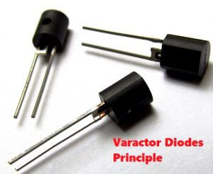
These devices are commonly used in communication systems. Varactor diodes are also referred to as varicaps or tuning diodes.

varactor-diode-symbol

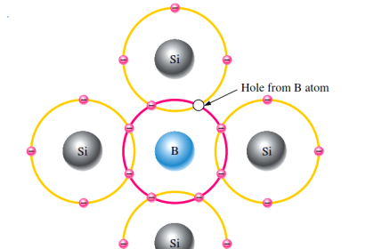
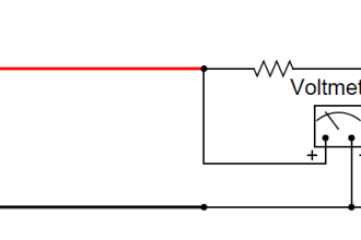
A varactor is a diode that always operates in reverse bias and is doped to maximize the inherent capacitance of the depletion region. The depletion region acts as a capacitor dielectric because of its nonconductive characteristic. The p and n regions are conductive and act as the capacitor plates, as illustrated in Figure.

 reverse-biased varactor diode

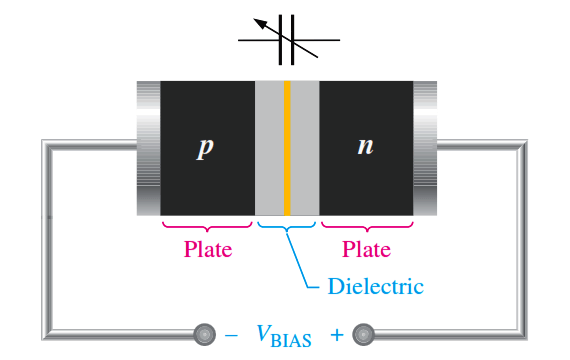
Fig : The reverse-biased varactor diode acts as a variable capacitor.

Basic Operation

Capacitance is determined by the parameters of plate area (A), dielectric constant (P), and plate separation (d), as expressed in the following formula:

varactor-diodes-capacitance

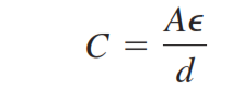
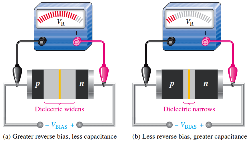
As the reverse-bias voltage increases, the depletion region widens, effectively increasing the plate separation, thus decreasing the capacitance. When the reverse-bias voltage decreases, the depletion region narrows, thus increasing the capacitance. This action is shown in Figure (a) and (b). A graph of diode capacitance (CT) versus reverse voltage for a certain varactor is shown in Figure (c). For this particular device, CT varies from 30 pF to slightly less than 4 pF as VR varies from 1 V to 30 V.

varactor-diode-operation

In a varactor diode, these capacitance parameters are controlled by the method of doping near the pn junction and the size and geometry of the diode’s construction. Nominal varactor capacitances are typically available from a few picofarads to several hundred picofarads.

Varactor diode characteristics

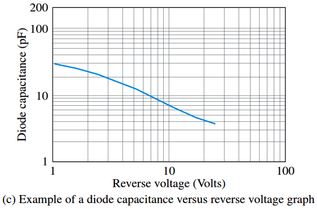
Fig : Varactor diode capacitance varies with reverse voltage.

Applications

A major application of varactors is in tuning circuits. For example, VHF, UHF, and satellite receivers utilize varactors. Varactors are also used in cellular communications.

Don't Miss Our Updates
Be the first to get exclusive content straight to your email.
We promise not to spam you. You can unsubscribe at any time.
Invalid email address
You've successfully subscribed !

Continue Reading

Dependent Current Source
Types of Resistors
Forward Bias & Reverse Bias Diode Working Animation
What is Kirchhoff’s Voltage Law
Transistor as a Switch Working Principle
Electron Gun of Cathode Ray Tube
Share This Article
Facebook Whatsapp Whatsapp LinkedIn Copy Link
Share
Leave a Comment

Leave a Reply Cancel reply

Your email address will not be published. Required fields are marked *

Stay Connected

128.3kFollowersLike
69.1kFollowersFollow
210kSubscribersSubscribe
38kFollowersFollow

Categories

Explore More

Different Types of Diodes
Half Wave Rectifier Principle
Band Gap for Semiconductor Materials
Phototransistor Working Principle
PMMC Temperature Compensation
Series and Parallel Resistors
Full Wave Voltage Doubler using Diodes
Peak Inverse Voltage of Center Tap Rectifier

Keep Learning

Permanent magnet moving coil instruments (PMMC)

Permanent Magnet Moving Coil Instruments (PMMC)

Zener Diode Limiter Working

Zener Diode Limiter

Independent-Voltage-Source-circuit-ideal-battery

Circuit Elements and Types of Circuits

Diode-positive-limiter

Positive & Negative Diode Clippers

Transistor Load Line Analysis

Transistor Load Line Analysis

diode-basic-structure-symbol

Forward Bias & Reverse Bias of a Diode

How a Multi Color LED Works

How a Multi Color LED Works ?

Transistor-cut-off-saturation-active-regions

Transistor Cut off, Saturation & Active Regions

Learn More

Power Electronics Objective Questions

Thyristor Rating Objective Questions and Answers

What is Capillary Tubing

What is Capillary Tubing? – Advantages and Disadvantages

Electrical Machines Questions and Answers

Synchronous Machine Multiple Choice Questions

Gas Turbine Interview Questions and Answers

Gas Turbine Interview Questions and Answers

How does the IIoT work - Industrial Internet of Things

How does the IIoT work? – Industrial Internet of Things

Instrumentation Engineering Root Cause Analysis

Instrumentation Engineering Problems Solved – Root Cause Analysis

Parallel RLC Circuit

Resonance, Resonant Frequency, Series and Parallel Resonance

IGBT Switching Characteristics

IGBT – Symbol, Construction, Working, Characteristics, Advantages

Menu

  • About
  • Privacy Policy
  • Copyright

Quick Links

  • Learn PLC
  • Helping Hand
  • Part Time Job

YouTube Subscribe

Follow US
All rights reserved. Reproduction in whole or in part without written permission is prohibited.
Welcome Back!

Sign in to your account

Username or Email Address
Password

Lost your password?