Categories: Electronic Devices & Circuits

Troubleshooting a Biased Transistor

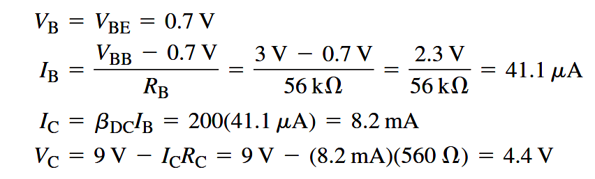
Several faults can occur in a simple transistor bias circuit. Possible faults are open bias resistors, open or resistive connections, shorted connections, and opens or shorts internal to the transistor itself. The above Figure is a basic transistor bias circuit with all voltages referenced to ground.

Troubleshooting a Biased Transistor

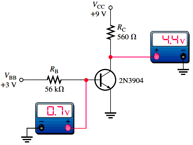
The two bias voltages are VBB = 3 V and VCC = 9 V. The correct voltage measurements at the base and collector are shown. Analytically, these voltages are verified as follows. A bDC = 200 is taken as midway between the minimum and maximum values of hFE given on the datasheet for the 2N3904 (Note : Download transistor datasheet for reference). A different hFE (bDC), of course, will produce different results for the given circuit.


You've successfully subscribed !
Share

Recent Articles

  • PLC Tutorials

Example PLC Program to Control a Pump based on Level Sensors

Learn an example PLC program to control a pump based on level sensors using ladder…

2 weeks ago
  • PLC Tutorials

PLC Timer Application in Security Camera Recording

In the PLC timer application for security camera recording, when motion is detected then camera…

2 weeks ago
  • PLC Tutorials

Batch Mixing with PLC Ladder Logic Program

In this example, we will learn batch mixing with PLC ladder logic program using timer…

2 weeks ago
  • PLC Tutorials

PLC Example on Manufacturing Line Assembly

This PLC example on manufacturing line assembly is an intermediate-level PLC program prepared for the…

2 weeks ago
  • PLC Tutorials

PLC Programming Example with Pushbutton and Motor

In this article, you will learn the PLC programming example with pushbutton and motor control…

3 weeks ago
  • PLC Tutorials

Boolean Logic to PLC Programming

This article teaches how to convert Boolean logic to PLC programming ladder logic with the…

1 month ago