If an emitter resistor is added to the base-bias circuit, the result is emitter-feedback bias, as shown in Figure. The idea is to help make base bias more predictable with negative feedback, which negates any attempted change in collector current with an opposing change in base voltage. If the collector current tries to increase, the emitter voltage increases, causing an increase in base voltage because VB = VE + VBE.
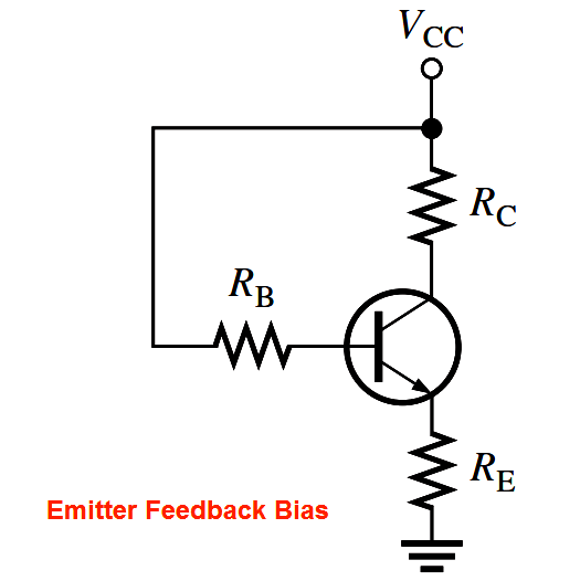
This increase in base voltage reduces the voltage across RB, thus reducing the base current and keeping the collector current from increasing. A similar action occurs if the collector current tries to decrease. While this is better for linear circuits than base bias, it is still dependent on βDC and is not as predictable as voltage-divider bias. To calculate IE, you can write Kirchhoff’s voltage law (KVL) around the base circuit.
PLC ladder logic design to control 3 motors with toggle switch and explain the program…
VFD simulator download: Master the online tool from the Yaskawa V1000 & programming software for…
The conveyor sorting machine is widely used in the packing industries using the PLC program…
Learn the example of flip-flop PLC program for lamps application using the ladder logic to…
In this article, you will learn the STAR DELTA programming using PLC controller to start…
Lube oil consoles of rotary equipment packages in industrial process plants are usually equipped with…

