The transformer voltage at the load side desired to be constant or as close to the design value. But the load voltage may vary according to current drawn by the load or supply voltage.
Secondary voltage = (supply voltage or primary voltage) / Turns ratio.
Based on the above equation to maintain constant secondary voltage/load voltage or as close to the desired value it is needed to change the turn’s ratio. The tap changer of the transformer performs this task to change the turn’s ratio. The tap changer basic function is that it removes or connects some portion of the winding to the load side or source side. Tap changer can be located on primary side or secondary side. However it will be placed on high voltage winding side.
Why tap changer is placed on high voltage side?
The tap changer is placed on high voltage side because:
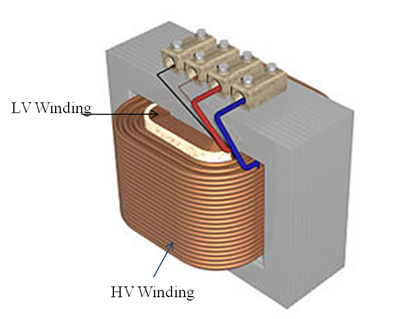
1.The HV winding generally wound over LV winding hence it is easier to access the HV winding turns instead of LV winding.
2.Because of high voltage the current through the HV winding is less compared to LV windings, hence there is less “wear” on the tap changer contacts. Due this low current, in on load tap changer the change over spark will be less.
Tap changer Primary side:
In this type the tap changer circuit is placed in primary side or supply side. As we know;
Turns ratio = secondary winding turns (Ns)/ primary winding turns (Np).
Secondary voltage = (supply voltage or primary voltage) / Turns ratio.
By the above formulas it is stated that if the primary turns decreases the turn’s ratio increases hence then secondary voltage decreases. Opposite for the reverse case i.e. primary turns increase leads to turns ratio decrease which increases the secondary voltage.
Figure shows the tap changer on primary winding with tap changing interval of 2.5 % per tap. With this we can understand three conditions:
2)If the supply voltage increases or load current decreases there will be an increase in supply voltage which is not desirable. At this case the tap position in the primary winding will rise towards positive direction i.e. +2.5%, and hence decreases the Np. This will increases the turns ratio (Ns/Np) further decreases the secondary voltage.
Consider the load voltage decreased then the tap changer shift towards negative side to increase the primary turns and hence decreases the turn’s ratio. The secondary voltage will increase to compensate the change.
Tap changer Secondary side:
In this the tap changer is placed in secondary side of the transformer. This type of taping is used in step-up transformer where low voltage winding is in primary side and high voltage winding is in secondary side. Figure shows the tap changer circuit on secondary side with tap interval of 2.5 %. In some distribution transformers the tap changer resolution can be up to 1% for fine adjustments.
In this the case is reverse compared to primary tap changer. To increase the secondary voltage the tap changer will move towards positive direction and it moves in negative direction to decrease the secondary voltage.
Lube oil consoles of rotary equipment packages in industrial process plants are usually equipped with…
Rotating equipment packages such as pumps, compressors, turbines need the lube oil consoles for their…
This article explains how to blink lights in ladder logic with a detailed explanation video…
In this article, a simple example will teach you the conversion from Boolean algebra to…
In this article, you will learn the PLC cooking timer example for kitchen automation using…
Learn an example PLC program to control a pump based on level sensors using ladder…


