Inst ToolsInst ToolsInst Tools
  • Courses
  • Automation
    • PLC
    • Control System
    • Safety System
    • Communication
    • Fire & Gas System
  • Instrumentation
    • Design
    • Pressure
    • Temperature
    • Flow
    • Level
    • Vibration
    • Analyzer
    • Control Valve
    • Switch
    • Calibration
    • Erection & Commissioning
  • Interview
    • Instrumentation
    • Electrical
    • Electronics
    • Practical
  • Q&A
    • Instrumentation
    • Control System
    • Electrical
    • Electronics
    • Analog Electronics
    • Digital Electronics
    • Power Electronics
    • Microprocessor
  • Request
Search
  • Books
  • Software
  • Projects
  • Process
  • Tools
  • Basics
  • Formula
  • Power Plant
  • Root Cause Analysis
  • Electrical Basics
  • Animation
  • Standards
  • 4-20 mA Course
  • Siemens PLC Course
Reading: Transformer Energy Losses & Efficiency
Share
Font ResizerAa
Inst ToolsInst Tools
Font ResizerAa
  • Courses
  • Design
  • PLC
  • Interview
  • Control System
Search
  • Courses
  • Automation
    • PLC
    • Control System
    • Safety System
    • Communication
    • Fire & Gas System
  • Instrumentation
    • Design
    • Pressure
    • Temperature
    • Flow
    • Level
    • Vibration
    • Analyzer
    • Control Valve
    • Switch
    • Calibration
    • Erection & Commissioning
  • Interview
    • Instrumentation
    • Electrical
    • Electronics
    • Practical
  • Q&A
    • Instrumentation
    • Control System
    • Electrical
    • Electronics
    • Analog Electronics
    • Digital Electronics
    • Power Electronics
    • Microprocessor
  • Request
Follow US
All rights reserved. Reproduction in whole or in part without written permission is prohibited.
Inst Tools > Blog > Electrical Machines > Transformer Energy Losses & Efficiency

Transformer Energy Losses & Efficiency

Last updated: March 9, 2016 2:03 pm
Editorial Staff
Electrical Machines
No Comments
Share
3 Min Read
SHARE

Transformers reduce the voltage of the electricity supplied by the utility to a level suitable for use by the electric equipment. Since all of the electricity used by a company passes through a transformer, even a small efficiency improvement will result in significant electricity savings. High-efficiency transformers are now available that can reduce total electricity use by approximately 1 percent. Reduced electricity use provides cost savings for a company.

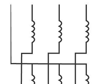
Two types of energy losses occur in transformers: load and no-load losses.

Load losses: result from resistance in the copper or aluminum windings. Load losses (also called winding losses) vary with the square of the electrical current (or load) flowing through the windings. At low loads (e.g. under 30 percent loading), core losses account for the majority of losses, but as the load increases, winding losses quickly dominate and account for 50 to 90 percent of transformer losses at full load. Winding losses can be reduced through improved conductor design, including proper materials selection and increases in the amount of copper conductor employed.

No-load losses: result from resistance in the transformer’s laminated steel core. These losses (also called core losses) occur whenever a transformer is energized and remain essentially constant regardless of how much electric power is flowing through it. To reduce core losses, high-efficiency transformers are designed with a better grade of core steel and with thinner core laminations than standard-efficiency models.

Total transformer losses are a combination of the core and winding losses. Unfortunately, some efforts to reduce winding losses increase core losses and vice versa. For example, increasing the amount of conductor used reduces the winding losses, but it may necessitate using a larger core, which would increase core losses. Manufacturers are developing techniques that optimize these losses based on the expected loading.

Annual energy losses and cost of these losses:

The annual energy losses of a transformer can be estimated from the following formula

Wloss = 8760(Po+Pk L2)

Where,

Wloss – is the annual energy loss in kWh.

Po – is the no-load loss in kW.

Pk – is the short-circuit loss (or load loss) in kW.

L – is the average per-unit load on the transformer.

8760 – is the number of hours in a year.

To calculate the cost of these losses, they need to be converted to the moment of purchase by assigning capital values, to be able to put them into the same perspective as the purchase price. This is called the Total Capitalized Cost of the losses, TCC loss. This can be calculated using the following formula

Transformer Losses

Where,

C – is the estimated average cost per kWh in each year.

i – is the estimated interest rate.

n – is the expected life time of the transformer.

Don't Miss Our Updates
Be the first to get exclusive content straight to your email.
We promise not to spam you. You can unsubscribe at any time.
Invalid email address
You've successfully subscribed !

Continue Reading

DC Motor Applications in Industries
Why Armature is placed on Stator for Synchronous machines
Electrical Machines Objective Questions
What is a transformer tap changer?
What happen When Synchronous Generator loss Excitation
Advantages and Disadvantages of Squirrel Cage Induction motor
Share This Article
Facebook Whatsapp Whatsapp LinkedIn Copy Link
Share
Leave a Comment

Leave a Reply Cancel reply

Your email address will not be published. Required fields are marked *

Stay Connected

128.3kFollowersLike
69.1kFollowersFollow
210kSubscribersSubscribe
38kFollowersFollow

Categories

Explore More

Stepper Motor Basics, Types, Modes, Wiring, Questions
Synchronous Motor Working Principle
BLDC Motor Vs AC Induction Motor
Zigzag Transformers Theory
Losses in a DC Generator
Parallel Operation of Alternators
Importance of Hysteresis Loop
Difference between Star and Delta Connections

Keep Learning

Induction Motor Operating Characteristics

Dead Time and Reclaim Time

What is Auto Reclosing?

Types of Transfomer Cooling Methods

DC motor speed control

DC Motor Speed Control

Squirrel Cage Induction Motor vs Slip Ring Induction Motor

Difference Between Squirrel Cage and Slip Ring Motors

Specific-Conductance-Calibration-Procedure

Types of AC Motors and DC Motors

Induction Motors Faults and Protection

Learn More

sulfur dioxide analyzer

Fluorescence

30 Concerns for Control System Philosophy (Industrial Automation)

30 Concerns for Process Control Systems Philosophy

FOUNDATION Fieldbus junction boxes

Fieldbus Cables

power factor correction equipment

Power Factor Controller (PFC) – Commissioning

Basics of Butterfly Valves

3-way-2-position-solenoid-valve-spring-return

Pneumatic Directional Control Valves

Calibrating Transmitter System One Seal with suppressed Zero

Calibrating Level Transmitter with Remote Seals

What is Multi-touch Technology

What is Multi-touch Technology? – Industrial Automation

Menu

  • About
  • Privacy Policy
  • Copyright

Quick Links

  • Learn PLC
  • Helping Hand
  • Part Time Job

YouTube Subscribe

Follow US
All rights reserved. Reproduction in whole or in part without written permission is prohibited.
Welcome Back!

Sign in to your account

Username or Email Address
Password

Lost your password?