Inst ToolsInst ToolsInst Tools
  • Courses
  • Automation
    • PLC
    • Control System
    • Safety System
    • Communication
    • Fire & Gas System
  • Instrumentation
    • Design
    • Pressure
    • Temperature
    • Flow
    • Level
    • Vibration
    • Analyzer
    • Control Valve
    • Switch
    • Calibration
    • Erection & Commissioning
  • Interview
    • Instrumentation
    • Electrical
    • Electronics
    • Practical
  • Q&A
    • Instrumentation
    • Control System
    • Electrical
    • Electronics
    • Analog Electronics
    • Digital Electronics
    • Power Electronics
    • Microprocessor
  • Request
Search
  • Books
  • Software
  • Projects
  • Process
  • Tools
  • Basics
  • Formula
  • Power Plant
  • Root Cause Analysis
  • Electrical Basics
  • Animation
  • Standards
  • 4-20 mA Course
  • Siemens PLC Course
Reading: Temperature Compensation for Pressure Measurement
Share
Font ResizerAa
Inst ToolsInst Tools
Font ResizerAa
  • Courses
  • Design
  • PLC
  • Interview
  • Control System
Search
  • Courses
  • Automation
    • PLC
    • Control System
    • Safety System
    • Communication
    • Fire & Gas System
  • Instrumentation
    • Design
    • Pressure
    • Temperature
    • Flow
    • Level
    • Vibration
    • Analyzer
    • Control Valve
    • Switch
    • Calibration
    • Erection & Commissioning
  • Interview
    • Instrumentation
    • Electrical
    • Electronics
    • Practical
  • Q&A
    • Instrumentation
    • Control System
    • Electrical
    • Electronics
    • Analog Electronics
    • Digital Electronics
    • Power Electronics
    • Microprocessor
  • Request
Follow US
All rights reserved. Reproduction in whole or in part without written permission is prohibited.
Inst Tools > Blog > Pressure Measurement > Temperature Compensation for Pressure Measurement

Temperature Compensation for Pressure Measurement

Last updated: February 29, 2020 11:07 am
Editorial Staff
Pressure Measurement
No Comments
Share
5 Min Read
SHARE

Have you ever wondered how much impact environmental temperature has on your pressure sensors? Nearly every pressure sensor has some sort of environmental temperature specification on its data sheet. This technical note explains the environmental temperature effects on pressure sensors, quantifying the impact, and ways to minimize the impact.

Why pressure sensors are impacted by environmental temperature changes ?

Much like anything else in the physical measurement world, pressure sensors are subject to changes in environmental conditions. Temperature effects tend to have the largest impact on pressure measurement accuracy.

Temperature effects directly influence the pressure sensor and the circuitry used to measure the sensor. Digital pressure sensors use electronic circuits which provide an analog output proportional to the inlet pressure.

There are three factors of a sensor’s circuitry that are affected by environmental temperature changes: zero pressure output voltage, pressure sensitivity span and bridge resistance. Temperature-compensated sensors employee some techniques to correct for and minimize the impact of temperature changes on these factors.

To understand the environmental temperature effect on your sensor, it is helpful to first understand some common terms you may see on a pressure sensor specification sheet.

Operating Temperature Range:

This is the temperature range over which the sensor can be used without causing damage.

Temperature Compensated Accuracy Range:

This refers to the environmental temperature range over which the accuracy of the sensor is applicable.

Temperature Coefficient:

An additional error that needs to be considered when used outside of the temperature compensated accuracy range.

Many sensors are only tested and calibrated at laboratory temperatures. In this case, the temperature coefficient will need to be considered in the measurement accuracy when using the sensor outside of laboratory temperatures.

Quantifying the environmental temperature effect

So how much will the ambient temperature impact your measurement accuracy? Well, this will depend on the temperature compensated accuracy range and the temperature coefficient.

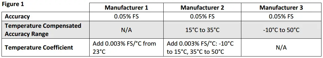
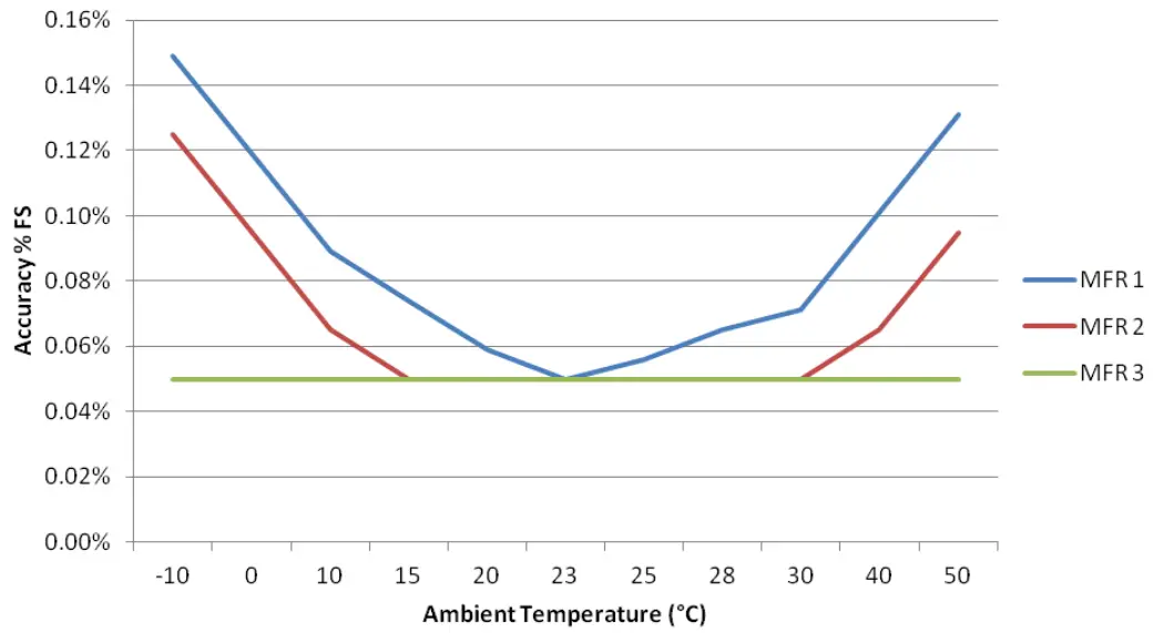
To demonstrate this, let’s consider three different gauges. As you can see from the specifications below (figure 1), they all have the same accuracy specification of 0.05% FS.

However, as you consider the temperature compensated accuracy range and the temperature coefficient you’ll see a fairly large variation between the three gauges.

Pressure Sensor Compensation

The graph below shows the total specified accuracy when considering the temperature effects on the pressure gauges. As you can see in one case here, the lack of temperature compensation and inclusion of the temperature coefficient specification more than triple the 0.05% FS accuracy specification.

Pressure Sensor Temperature Effects

Temperature compensation test results

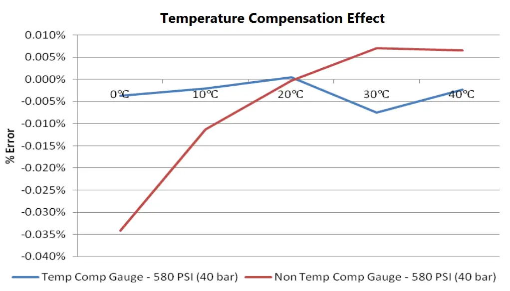
To further show temperature compensation has real effect, we placed a non-temperature compensated pressure gauge in a temperature chamber and pressure tested it from 0 to 580 psi (0 to 40 bar) and over the environmental temperature range of 0°C to 40°C. We then performed the same test on a temperature compensated gauge.

As you may expect—the higher the pressure, the larger the impact from the environmental temperature. Below is a chart comparing the non-temperature compensated gauge with the temperature compensated gauge

Pressure Sensor Temperature Effects - 2

Minimizing environmental temperature error

The temperature effect on a pressure sensor will be negligible when used at the same laboratory temperature in which it was calibrated. This, however, is often not practical for your measurements.

With sensor technology advances, we have found a variety of ways to minimize the temperature effect on pressure sensors and with confidence define a large temperature compensated accuracy range.

First, regularly zero your digital pressure gauges. By zeroing the pressure gauge, you are aligning the zero pressure output voltage to the current environmental conditions. You should only zero the pressure gauge when you do not have any inlet pressure on the gauge.

Because each sensor is unique and performs differently due to environmental temperature changes, at Additel, we pressure test every sensor in a thermal chamber at different temperatures so we understand its pressure performance relative to environmental changes.

Each sensor contains a temperature-compensated circuit which we load coefficients representing the temperature testing of the gauge. This allows for you to confidently use our sensors over the range -10°C to 50°C without having to add a temperature coefficient error to the accuracy.

Article by : Jon Sanders

Source : additel

Don't Miss Our Updates
Be the first to get exclusive content straight to your email.
We promise not to spam you. You can unsubscribe at any time.
Invalid email address
You've successfully subscribed !

Continue Reading

Impulse Line – Purpose & Tapping Point Location
Fine Wire Strain Gauge Principle
Effects of Symmetric and Asymmetric Capillary Tube Pressure Measurement
Bellows
Well Manometer Principle
When to use a Diaphragm Seal?
Share This Article
Facebook Whatsapp Whatsapp LinkedIn Copy Link
Share
Leave a Comment

Leave a Reply Cancel reply

Your email address will not be published. Required fields are marked *

Stay Connected

128.3kFollowersLike
69.1kFollowersFollow
210kSubscribersSubscribe
38kFollowersFollow

Categories

Explore More

DP Transmitter Applications
Bourdon Tube Pressure Gauge Working Principle Animation
Pressure Gauge Maintenance and Troubleshooting
Pressure Gauge Accessories Questions and Answers
Electronic Pressure Sensors Principle
Pressure Gauges with Capsule Sensor Principle
Types of Pressure Measuring Scales
Pressure Gauge Selection

Keep Learning

Differential Pressure Sensor for Filtration Monitoring

Differential Pressure Sensor for Filtration Monitoring

Sensor Trim and Output Trim in Smart Transmitter

What is Sensor Trim and Output Trim in Smart Transmitter?

Why are Impulse Lines often Installed in a Sloping Manner (Angle)

Why are Impulse Lines often Installed in a Sloping Manner?

DP transmitter with Manifold

Pressure Transmitter Manifolds

Instrument Protection Methods: Seals

Instrumentation Impulse Lines

All About Instrumentation Impulse Lines

Pressure Measurement using Manometer

Pressure Measurement using Manometer

Advantages of Pneumatic Systems in the Automotive Industry

Advantages of Pneumatic Systems in the Automotive Industry

Learn More

PLC Ladder Logic for Lube Oil Pump Motor

PLC Ladder Logic for Lube Oil Pump Motor

Comparison of Half wave Rectifiers and Full wave Rectifiers

Comparison of Half wave Rectifiers and Full wave Rectifiers

Structured Text Selector Machine Logic

Write a PLC Program for Selector Machine using Structured Text

Single Line Diagram (SLD) Example

Electrical Drawings

AC Generator Operation

AC Generator Theory

Extended Timer Logic in PLC

Extended Timer Logic in PLC

PLC Program for Valves

PLC Pump Permissive Interlocks

Difference between Current Transformer and Potential Transformer

Difference between Current Transformer and Potential Transformer

Menu

  • About
  • Privacy Policy
  • Copyright

Quick Links

  • Learn PLC
  • Helping Hand
  • Part Time Job

YouTube Subscribe

Follow US
All rights reserved. Reproduction in whole or in part without written permission is prohibited.
Welcome Back!

Sign in to your account

Username or Email Address
Password

Lost your password?