Stator view
Three-phase sinusoidal balanced excitation in 3 stator phases produces a sinusoidally distributed field rotating at the excitation frequency ωs. This field can be viewed as being created by a single equivalent sinusoidal winding which is excited with dc current and which is also rotating. The flux density distribution is represented here by the state vector Bm (or, equivalently, by the magnetizing current Im). It is portrayed in the air gap with shaded colors for which the more intense the color the higher the field intensity and where blues point to the rotor and reds to the stator.
This distribution rotates at the stator frequency ωs as seen from the stator stationary frame and at the slip frequency ωslip=ωs– ωm with respect to the rotor turning at ωm, thereby generating sinusoidal voltages of slip frequency in the rotor bars and corresponding sinusoidal slip-frequency currents with a delay due to the presence of rotor leakage. This rotor current distribution rotates at ωslip with respect to the rotor and atωs with respect to the stationary stator observer. It can thus be represented by the rotor space vector Ir. Since Bm (or Im) cannot change, the stator current Is must include a component IR = – Ir .

Rotor view
In the rotor reference frame, the rotor speed ωm is effectively zero. The flux density wave represented by the space vector Bm (or, equivalently, by the magnetizing current Im) now moves at slip speed with respect to the rotor inducing in the rotor bar slip-frequency currents which are sinusoidally distributed. The result is seen as a sinusoidally distributed rotor winding whose axis is represented by the space vector Ir; both winding and space vector Ir rotate at the slip speed ωsl . Similarly, the stator space vector IR which compensates for the rotor effects and the resultant stator current Is = IR + Imall move at slip speed.
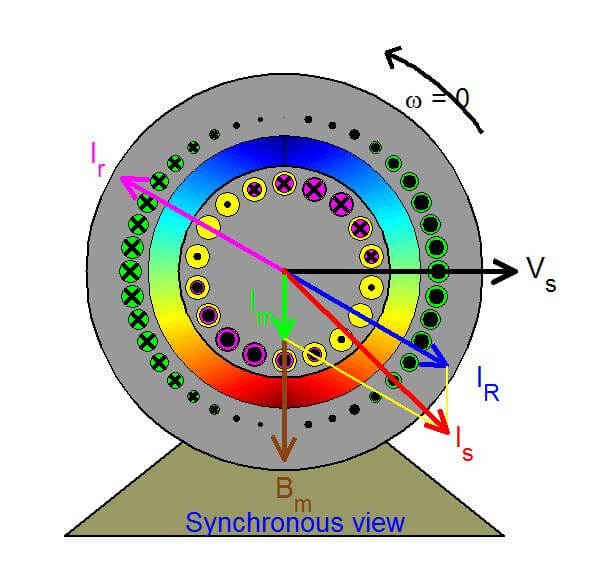
Synchronous view
In the synchronous reference frame, all variables appear as dc quantities in steady state. All space vectors are frozen in space in the shown fixed position based on the assumption that the original stationary and the synchronously rotating reference frames coincide at time t = 0. These vectors may then be directly associated with the (per-phase) phasors of the induction motor, combined in a phasor diagram, and interpreted by means of an equivalent cicuit made up of a magnetizing inductance in parallel with the rotor leakage inductance acting in series with a resistor.