The Snubber circuit is one type of dv/dt protection circuit of the thyristor.
With the help of snubber circuit, the false turn-on of a thyristor due to large dv/dt can be prevented.
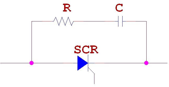
RC Snubber Circuit for SCR dv/dt Protection:
This type of snubber circuit consists of a series combination of resistance R and Capacitance C in parallel with a SCR.
Based on the above discussion we can say that simply a Capacitor C is sufficient to protect the SCR against dv/dt false triggering.
Then what is the purpose of resistance R?
In actual practice, R, C and the load current parameters should be such that
Normally R,S and load circuit parameters form an undamped circuit so that dv/dt is limited to acceptable values.
In some RC snubber circuits, a diode D used to connect in parallel with the resistor R. It is used for the purpose of bypass and thus giving improved dv/vt protection.
PLC ladder logic design to control 3 motors with toggle switch and explain the program…
VFD simulator download: Master the online tool from the Yaskawa V1000 & programming software for…
The conveyor sorting machine is widely used in the packing industries using the PLC program…
Learn the example of flip-flop PLC program for lamps application using the ladder logic to…
In this article, you will learn the STAR DELTA programming using PLC controller to start…
Lube oil consoles of rotary equipment packages in industrial process plants are usually equipped with…

