A proximity switch is one detecting the proximity (closeness) of some object. By definition, these switches are non-contact sensors, using magnetic, electric, or optical means to sense the proximity of objects.
A proximity switch will be in its “normal” status when it is distant from any detectable object.
Being non-contact in nature, proximity switches are often used instead of direct-contact limit switches for the same purpose of detecting the position of a machine part, with the advantage of never wearing out over time due to repeated physical contact.
Most proximity switches are active in design. That is, they incorporate a powered electronic circuit to sense the proximity of an object. Inductive proximity switches sense the presence of metallic objects through the use of a high-frequency magnetic field. Capacitive proximity switches sense the presence of non-metallic objects through the use of a high-frequency electric field. Optical proximity switches detect the interruption of a light beam by an object. Ultrasonic proximity switches sense the presence of dense matter by the reflection of sound waves.
Proximity Switch Symbol
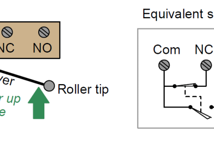
The schematic diagram symbol for a proximity switch with mechanical contacts is the same as for a mechanical limit switch, except the switch symbol is enclosed by a diamond shape, indicating a powered (active) device:
Many proximity switches, though, do not provide “dry contact” outputs. Instead, their output elements are transistors configured either to source current or sink current. The terms “sourcing” and “sinking” are best understood by visualizing electric current in the direction of conventional flow rather than electron flow.
The following schematic diagrams contrast the two modes of switch operation, using red arrows to show the direction of current (conventional flow notation). In both examples, the load being driven by each proximity switch is a light-emitting diode (LED):
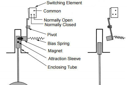
Principle of Operation:
Proximity Switch consists a sensor circuit and a driver circuit. The sensor circuit purpose is used to detect any near by objects. The sensor circuit sends an output High signal to the transistor based driver circuit when any object found near to the sensor circuit. The transistor based driver circuit may use NPN or PNP transistors and it depends on the application we use.
When a signal received from the sensor circuit, the transistor will be turned ON and the output will be ON. When the object is moved away from sensor circuit, the sensor output is OFF so transistor is OFF and the output will be OFF.
Note: The sensor circuit may contain a LC Resonant oscillator or a mutual induction based circuit. The LC Resonant oscillator generates a designed resonant oscillations continuously. whenever there is any metal object nearby to the sensors, the oscillations may vary and it depends on the object properties. This change in oscillations will be detected and generates an output either High or Low, nothing but object found or not.
Proximity Switch NPN Type
Note: The Red dot in the animation indicated the flow of current path.
Proximity Switch PNP Type
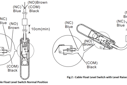
A common coloring convention for electronic proximity switches is brown for +V power supply, blue for ground (− pole of power supply), and black for the switched output signal. This convention is common to sinking and sourcing proximity switches alike.
An electronic switch designed to sink current through its signal wire is alternatively referred to as an NPN switch due to the type of transistor used in its output. Conversely, an electronic switch designed to source current through its signal wire may be referred to as a PNP switch.
The key to understanding these labels is to recognize the emitter terminal of the output transistor is always the one connected to the power supply rail. For a sinking switch, this means the emitter must connect to the negative rail, necessitating an NPN transistor to do the switching. For a sourcing switch, this means the emitter must connect to the positive rail, in which case only a PNP transistor will suffice.


Explained in a better way … Thanks
Please expalin PNP & NPN in a better way.
sir,
when i am making print. Header line Heading line (Animation Basics, Measuremetn… etc.) full design spot coming in between Aricals. So please do someting.
thanks.
Hi, Right now i am facing some problems with Print/Pdf options. Soon those will be solved. Thanks
Very good thing
AMAZING
What software did you use to stimulate this?