Suppose we have a PLC connected to three process switches as shown in this illustration:
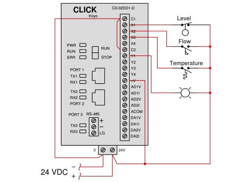
In the above Diagram :
Determine the switch actuation statuses (i.e. low versus high process stimulus) given the “live” display of the ladder logic program shown here:
Also, determine the status of the lamp connected to the PLC’s Y1 output.
Share Your Answer / Comments
Credits : Tony R. Kuphaldt – under CC BY 1.0
Lube oil consoles of rotary equipment packages in industrial process plants are usually equipped with…
Rotating equipment packages such as pumps, compressors, turbines need the lube oil consoles for their…
This article explains how to blink lights in ladder logic with a detailed explanation video…
In this article, a simple example will teach you the conversion from Boolean algebra to…
In this article, you will learn the PLC cooking timer example for kitchen automation using…
Learn an example PLC program to control a pump based on level sensors using ladder…

