Suppose we have a PLC connected to three process switches as shown in this illustration:
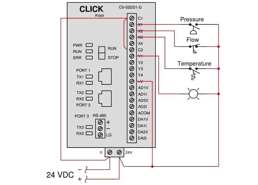
In the above diagram :
Determine the switch actuation statuses (i.e. low versus high process stimulus) given the “live” display of the ladder logic program shown here:
Also, determine the status of the lamp connected to the PLC’s Y1 output.
Share Your Answer / Comments
Credits : Tony R. Kuphaldt – under CC BY 1.0
Learn an example PLC program to control a pump based on level sensors using ladder…
In the PLC timer application for security camera recording, when motion is detected then camera…
In this example, we will learn batch mixing with PLC ladder logic program using timer…
This PLC example on manufacturing line assembly is an intermediate-level PLC program prepared for the…
In this article, you will learn the PLC programming example with pushbutton and motor control…
This article teaches how to convert Boolean logic to PLC programming ladder logic with the…

