Inst ToolsInst ToolsInst Tools
  • Ask
  • Courses
  • Videos
  • Q & A
    • Interview
      • Instrumentation
      • Electronics
      • Electrical
      • Practical Questions
    • MCQ
      • Instrumentation MCQ
      • Electrical MCQ
      • Electronics MCQ
      • Control Systems MCQ
      • Analog Electronics MCQ
      • Digital Electronics MCQ
      • Power Electronics MCQ
      • Microprocessor MCQ
      • Multiple Choice Questions
  • EE
    • Electronics
      • Electronics Q & A
      • Electronic Basics
      • Electronic Devices & Circuits
      • Electronics Animation
      • Digital Electronics
    • Electrical
      • Electrical Basics
      • Electrical Q & A
      • Power Electronics
      • Electrical Machines
      • Electrical Animation
      • Power Systems
      • Switchgear & Protection
      • Transmission & Distribution
  • Measure
    • Control Valves
    • Calibration
    • Temperature
    • Pressure
    • Flow
    • Level
    • Analyzers
    • Switches
    • Vibration
    • Solenoid Valve
  • Control
    • PLC Tutorials
    • Control Systems
    • Safety Instrumented System (SIS)
    • Communication
    • Fire & Gas System
  • More
    • Design
    • Tools
    • Animation
    • Basics
    • Formulas
    • Standards
    • TextBooks
    • Common
    • Software
    • Excel Tools
    • Erection & Commissioning
    • Process Fundamentals
    • Videos
    • Books
Search
All rights reserved. Reproduction in whole or in part without written permission is prohibited.
Reading: Pressure Level Transmitter Problems
Share
Notification Show More
Font ResizerAa
Inst ToolsInst Tools
Font ResizerAa
  • Courses
  • PLC Tutorials
  • Control Systems
Search
  • Ask
  • Courses
  • Videos
  • Q & A
    • Interview
    • MCQ
  • EE
    • Electronics
    • Electrical
  • Measure
    • Control Valves
    • Calibration
    • Temperature
    • Pressure
    • Flow
    • Level
    • Analyzers
    • Switches
    • Vibration
    • Solenoid Valve
  • Control
    • PLC Tutorials
    • Control Systems
    • Safety Instrumented System (SIS)
    • Communication
    • Fire & Gas System
  • More
    • Design
    • Tools
    • Animation
    • Basics
    • Formulas
    • Standards
    • TextBooks
    • Common
    • Software
    • Excel Tools
    • Erection & Commissioning
    • Process Fundamentals
    • Videos
    • Books
Follow US
All rights reserved. Reproduction in whole or in part without written permission is prohibited.
Inst Tools > Blog > Practical Questions > Pressure Level Transmitter Problems

Pressure Level Transmitter Problems

Last updated: September 20, 2018 12:02 pm
Editorial Staff
Practical Questions
1 Comment
Share
5 Min Read
SHARE

Pressure Level Transmitter Problems

Question :

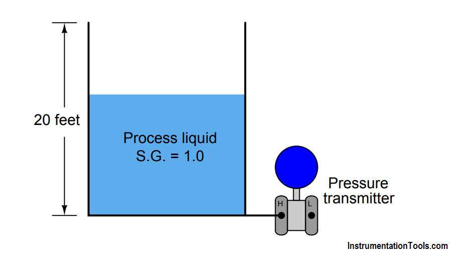
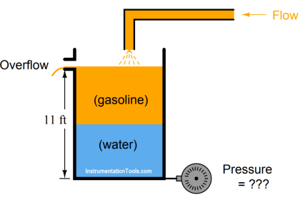
A vessel holding some process liquid needs to have its level monitored. The range of level in this vessel is 0 to 20 feet, and the process liquid has a specific gravity of 1.0 (like water). Someone decides to attach a pressure transmitter to the bottom of the vessel to infer level from hydrostatic pressure like this:

Contents
Pressure Level Transmitter ProblemsQuestion :Answer :

Pressure based Level Measurement

Later, a top is added to this vessel to keep rain from entering in. Unfortunately, though, this process liquid tends to emit vapor which will be trapped by the closed vessel and create a pressure inside of it. A small vent is added to the top of the vessel to permit the vapor to escape, but it is a small vent, not big enough to ensure a total absence of vapor pressure buildup at all times:

problem in level measurement

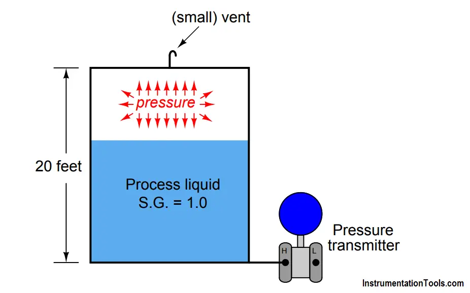
What problem in level measurement will result from there being an occasional vapor pressure buildup inside this vessel? How may this problem be corrected so that the liquid level will be accurately measured at all times?

Answer :

Any vapor pressure will be sensed by the transmitter and interpreted as increased liquid level!

Two solutions to this problem:

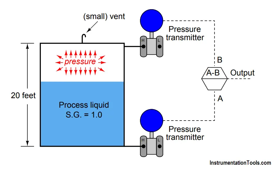
  1. Use two transmitters (one at top of vessel, one at bottom) and electronically subtract their output signals.
  2. Connect the “Low” side of the one ∆P transmitter to the top of the vessel to naturally compensate for vapor pressure.

Since the transmitter infers level from the amount of pressure sensed at the bottom of the vessel, any vapor pressure buildup inside the vessel will be falsely interpreted as additional liquid level, since the transmitter senses the sum total of hydrostatic pressure plus any vapor pressure trapped inside the vessel.

For example, if the process liquid level were at 10 feet (50% of range), the hydrostatic pressure generated by the liquid column would be 120 inches W.C., assuming a specific gravity of 1.0, equal to water. If, however, the vessel contained a vapor pressure equal to 15 inches W.C., this pressure would add with the 120 inches W.C. of pressure generated by liquid head to create 135 inches W.C. of total pressure sensed by the transmitter.

As a result, the transmitter would “think” it was detecting a liquid level of 11.25 feet (135 inches high) instead of the true level of 10 feet (120 inches high). Essentially, any vapor pressure in the vessel results in a “zero” shift of the transmitter’s indication.

In many applications, the gas pressure inside a vessel far exceeds the hydrostatic pressure generated by the column of liquid inside of it, so this problem can be a very serious one in level measurement. We need to fully understand the nature of the problem and how to solve it in order to successfully measure liquid level in many industrial applications.

The solution to this dilemma is to measure the difference in pressure between the top and bottom of the vessel. We could do this by using two pressure transmitters, one at the top and one at the bottom, and detect hydrostatic pressure by subtracting the top transmitter’s measurement from the bottom transmitter’s measurement. A computer/microcontroller may be used to perform the mathematical subtraction of signals:

Two Differential Pressure Transmitters

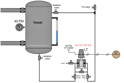
Another, more elegant method, incorporates a differential pressure transmitter with pipe connections to both ends of the vessel. This solution performs the subtraction mechanically, by directly exposing the transmitter’s sensing element to the difference of two applied pressures:

differential pressure transmitter solution

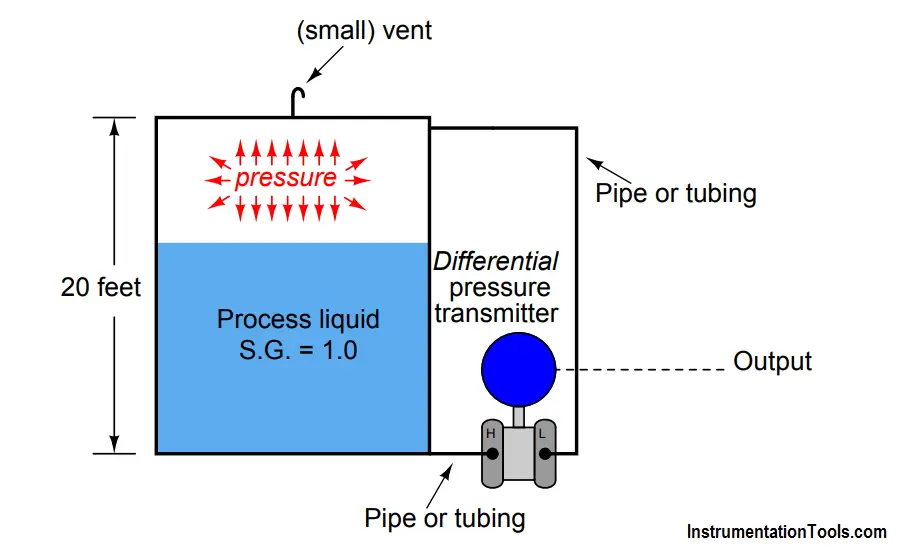
Because the differential pressure transmitter solution requires only one sensing instrument rather than two, and results in better accuracy because we are only dealing with the inaccuracies of a single instrument rather than the compounded inaccuracies of two instruments (three, if you include the subtraction unit), the differential, or “d/p” solution is the one more widely used.

In this particular level measurement application, a differential pressure instrument would have the exact same calibration points (lower and upper range-values) as a “normal” pressure transmitter connected to an open vessel.

Also Read : DP Transmitter Principle

Don't Miss Our Updates
Be the first to get exclusive content straight to your email.
We promise not to spam you. You can unsubscribe at any time.
Invalid email address
You've successfully subscribed !
Resistance Temperature Detector (RTD) Questions – 2
Pneumatic Force Balance Instrument
Surface-mounted Water Pump
Solenoid Valves Questions & Answers – 4
Air Pressure Inside the Tank
Share This Article
Facebook Whatsapp Whatsapp LinkedIn Copy Link
Share
1 Comment
  • Sushant gaikwad says:
    September 22, 2018 at 9:42 pm

    In this article complete solution for closed tank using dp transmitter not elaborated clearly. The questions arises that for the explanation given above for dp transmitter what will be the calibration range?

    Reply

Leave a Reply Cancel reply

Your email address will not be published. Required fields are marked *

Stay Connected

128.3kFollowersLike
69.1kFollowersFollow
208kSubscribersSubscribe
38kFollowersFollow

Categories

Recent Comments

  • Guifty Shimica on Top Non-PLC Certification Courses for Automation Professionals
  • Guifty Shimica on Top Non-PLC Certification Courses for Automation Professionals
  • MIHARITSOA Aina Sitraka on Top Non-PLC Certification Courses for Automation Professionals
  • Vaishnavi on Free Instrumentation Course for Trainee Engineers

Related Articles

Inductive proximity switches

How to Connect Proximity Switch (Source Type) to Make LED ON ?

Electronic Pressure Sensor with Bourdon Tube and LVDT

Electronic Pressure Sensor with Bourdon Tube and LVDT

Practical Control Systems Questions & Answers - 2

Practical Process Control System Questions & Answers – 2

Identify Problem with Oily Water Filter Instrumentation

Identify Problem with Oily Water Filter Instrumentation

Problem on Solar Hot Air Collector and Variable Speed Fan

Problem on Solar Hot Air Collector and Variable Speed Fan

Fisher model 546 I to P transducer

Fisher model 546 I/P transducer

Determine Level of Liquid in the Vessel and its Specific Gravity

Determine Level of Liquid in the Vessel and its Specific Gravity

Transmitter Questions

Practical Process Control System Questions & Answers – 4

More Articles

Automatic Transfer Switch

Automatic Transfer Switch (ATS) Using Classic Control Circuit

Structured Text Automatic Gate Logic

Structured Text PLC Programming for Automatic Gate Control

PID Controller Graph - 3

PID Controllers Graphical Analysis

Industrial IoT Job Roles and Responsibilities

IoT Engineer Job Roles and Responsibilities

How to export in Vijeo Designer

Vijeo Designer software – Import and Export

Pressure Switch Questions

Pressure Switch Questions

Single-acting Pneumatic Cylinder operation with Limit Switch

Single-acting Pneumatic Cylinder Operation with Limit Switch

Electrical Machines Questions and Answers

Voltage Regulation of Transformer

Follow US
All rights reserved. Reproduction in whole or in part without written permission is prohibited.
Welcome Back!

Sign in to your account

Username or Email Address
Password

Lost your password?