Practical Questions

Practical Process Control System Questions & Answers – 6

This water filter level control system uses an ultrasonic level transmitter to sense the level of water in the filter, and a controller to drive a motor-actuated valve introducing raw water to be filtered:

water filter level control system

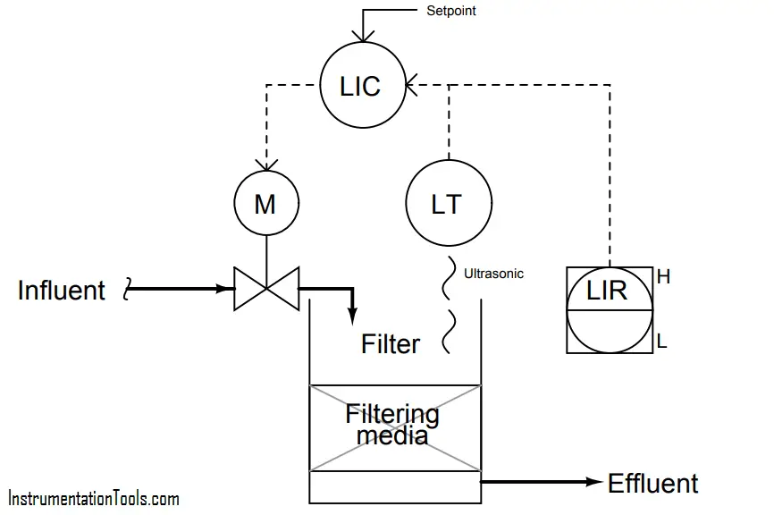
Assuming a direct-acting level transmitter (increasing filter level = increasing signal), and a signal-toopen control valve (increasing controller output signal = wider open valve), determine whether the level controller needs to be configured for direct-action or reverse-action, and explain your reasoning. Annotate the diagram with “+” and “−” symbols next to the PV and SP controller inputs to show more explicitly the relationships between the controller inputs and output.

Next, determine the response of the controller to the following situations. In other words, determine what the controller’s output signal will do when this water level control system is affected in the following ways:

  • A sudden increase in effluent flow rate (clean water demand)
  • Level transmitter fails high (indicating 100% full water level)
  • Control valve actuator fails, driving valve fully open (ignoring controller signal)

More Questions :

  1. Re-draw the diagram for this water filter level control system, replacing the controller (circle) with an op-amp symbol (triangle), determining the “+” and “−” input assignments on the opamp for PV and SP.
  2. Explain why level control is important in a water filter such as this.
  3. What do the “H” and “L” symbols near the LIR represent?

Answer :

This controller needs to be reverse-acting:

This re-drawing of the control system uses an opamp symbol in place of the ISA-standard circle used to represent a loop controller:

  • A sudden increase in effluent flow rate (clean water demand): controller output increases
  • Level transmitter fails high (indicating 100% full water level): controller output decreases
  • Control valve actuator fails, driving valve fully open (ignoring controller signal): controller output decreases

Share Your Answers via Comments

More Questions & Answers :
Practical Process Control System Questions & Answers – 1
Practical Process Control System Questions & Answers – 2
Practical Process Control System Questions & Answers – 3
Practical Process Control System Questions & Answers – 4
Practical Process Control System Questions & Answers – 5
Practical Process Control System Questions & Answers – 6
Practical Process Control System Questions & Answers – 7
Practical Process Control System Questions & Answers – 8
Practical Process Control System Questions & Answers – 9
Practical Process Control System Questions & Answers – 10
You've successfully subscribed !
Share

Recent Articles

  • PLC Tutorials

PLC Ladder Logic Design: Control 3 Motors with Toggle Switch

PLC ladder logic design to control 3 motors with toggle switch and explain the program…

3 weeks ago
  • PLC Tutorials

VFD Simulator Download – Free Yaskawa V1000 Software

VFD simulator download: Master the online tool from the Yaskawa V1000 & programming software for…

3 days ago
  • PLC Tutorials

Conveyor Sorting Machine PLC Program with Calculation Function

The conveyor sorting machine is widely used in the packing industries using the PLC program…

6 days ago
  • PLC Tutorials

Example of Flip-Flop PLC Program for Lamps Application

Learn the example of flip-flop PLC program for lamps application using the ladder logic to…

6 days ago
  • PLC Tutorials

STAR DELTA Programming using PLC Controller

In this article, you will learn the STAR DELTA programming using PLC controller to start…

7 days ago
  • Instrumentation Design

Single and Three Phase Immersion Electrical Heaters Wiring Circuits

Lube oil consoles of rotary equipment packages in industrial process plants are usually equipped with…

4 days ago