Inst ToolsInst ToolsInst Tools
  • Courses
  • Automation
    • PLC
    • Control System
    • Safety System
    • Communication
    • Fire & Gas System
  • Instrumentation
    • Design
    • Pressure
    • Temperature
    • Flow
    • Level
    • Vibration
    • Analyzer
    • Control Valve
    • Switch
    • Calibration
    • Erection & Commissioning
  • Interview
    • Instrumentation
    • Electrical
    • Electronics
    • Practical
  • Q&A
    • Instrumentation
    • Control System
    • Electrical
    • Electronics
    • Analog Electronics
    • Digital Electronics
    • Power Electronics
    • Microprocessor
  • Request
Search
  • Books
  • Software
  • Projects
  • Process
  • Tools
  • Basics
  • Formula
  • Power Plant
  • Root Cause Analysis
  • Electrical Basics
  • Animation
  • Standards
  • 4-20 mA Course
  • Siemens PLC Course
Reading: Practical Process Control System Questions & Answers – 2
Share
Notification Show More
Font ResizerAa
Inst ToolsInst Tools
Font ResizerAa
  • Courses
  • Design
  • PLC
  • Interview
  • Control System
Search
  • Courses
  • Automation
    • PLC
    • Control System
    • Safety System
    • Communication
    • Fire & Gas System
  • Instrumentation
    • Design
    • Pressure
    • Temperature
    • Flow
    • Level
    • Vibration
    • Analyzer
    • Control Valve
    • Switch
    • Calibration
    • Erection & Commissioning
  • Interview
    • Instrumentation
    • Electrical
    • Electronics
    • Practical
  • Q&A
    • Instrumentation
    • Control System
    • Electrical
    • Electronics
    • Analog Electronics
    • Digital Electronics
    • Power Electronics
    • Microprocessor
  • Request
Follow US
All rights reserved. Reproduction in whole or in part without written permission is prohibited.
Inst Tools > Blog > Practical Questions > Practical Process Control System Questions & Answers – 2

Practical Process Control System Questions & Answers – 2

Last updated: June 22, 2018 11:11 am
Editorial Staff
Practical Questions
2 Comments
Share
3 Min Read
SHARE

On the job, you are sent to troubleshoot a brand-new control system, consisting of a pneumatic liquid level transmitter connected to a pneumatic controller, which in turn drives a pneumatic control valve. The process vessel, piping, control valve, controller, and level transmitter are all brand-new: they even sport a fresh coat of paint.

Practical Control Systems Questions & Answers - 2

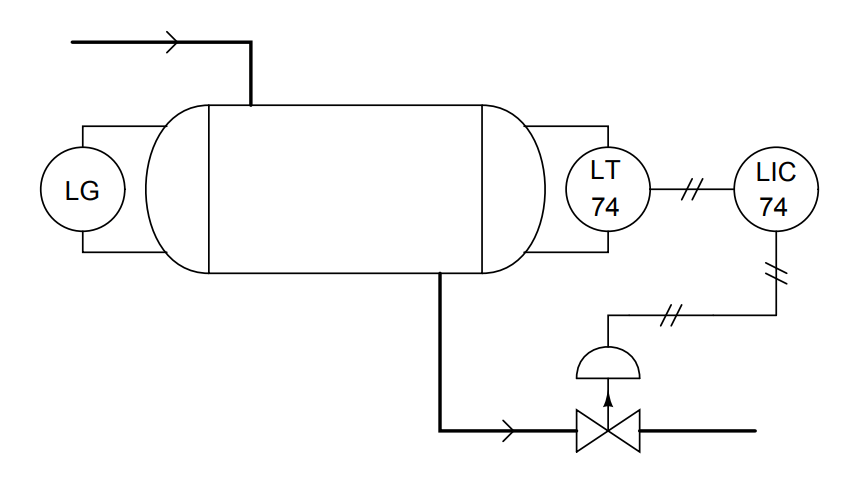
According to the unit operator, this level control system has never worked. As she shows you, the liquid level inside the vessel is so low that the level gauge (LG) registers empty, yet the controller is commanding the valve 100% open, which of course continues to drain the vessel and prevent any liquid level from accumulating.

Being versed in process control theory, you decide to check how the controller is configured. Looking inside the controller case, you notice the controller is set for direct action: an increasing PV results in an increasing output signal (MV), which will move the air-to-close valve more toward the “closed” state.

Realizing how to fix the problem, you reach inside the controller and move a lever that switches it into reverse action mode.

Explain why this fixes the problem.

More Questions :

  1. Explain the significance of the “newness” of this process. How would your assumptions differ if you saw this process vessel was old and rusted instead of shiny-new?
  2. How do you suppose the controller got to be mis-configured in the first place?
  3. What would have to be different in this control system to permit a direct-acting controller instead of a reverse-acting controller?
  4. Suppose you did not discover the controller’s action set for direct action. If the controller had been left in manual mode instead of automatic mode, could this account for the problems exhibited by this system?

Share Your Answers via Comments

More Questions & Answers :
Practical Process Control System Questions & Answers – 1
Practical Process Control System Questions & Answers – 2
Practical Process Control System Questions & Answers – 3
Practical Process Control System Questions & Answers – 4
Practical Process Control System Questions & Answers – 5
Practical Process Control System Questions & Answers – 6
Practical Process Control System Questions & Answers – 7
Practical Process Control System Questions & Answers – 8
Practical Process Control System Questions & Answers – 9
Practical Process Control System Questions & Answers – 10
Don't Miss Our Updates
Be the first to get exclusive content straight to your email.
We promise not to spam you. You can unsubscribe at any time.
Invalid email address
You've successfully subscribed !

Continue Reading

Identify the Problem in the PLC Program
Draw the Symbols for Liquid Level Measuring Instruments
Three-valve Manifold on Remote Seal DP Transmitter
A Question on Steam Drum Water Level Measurement
Pressure Switch Questions
Loop Powered Pressure Transmitter
Share This Article
Facebook Whatsapp Whatsapp LinkedIn Copy Link
Share
2 Comments
  • Mohammed Irfan Ali says:
    July 9, 2020 at 2:22 pm

    If the LG is showing empty but the controller is in 100% open that means it’s already in reverse action. And we have to change to direct action but the above summary contradicts.

    Reply
  • Rizwan Ashraf Adil says:
    July 17, 2024 at 12:18 am

    The issue is that the controller is configured for direct action, which means that as the process variable (PV) increases, the output signal (MV) also increases, closing the valve. However, in this specific application, the goal is to control the liquid level in the vessel. When the level is low (PV is low), the valve should be open to allow more liquid to flow in. Conversely, when the level is high (PV is high), the valve should close to prevent overfilling.

    By switching the controller to reverse action mode, you’ve effectively changed the controller’s behavior to:

    – Increasing PV (level) → Decreasing MV (valve opening)
    – Decreasing PV (level) → Increasing MV (valve opening)

    Now, when the level is low (PV is low), the controller output (MV) will increase, opening the valve to allow more liquid to flow in. As the level rises (PV increases), the controller output (MV) will decrease, closing the valve to prevent overfilling.

    This fixes the problem because the controller is now working in tandem with the valve to regulate the liquid level in the vessel. The reverse action mode ensures that the valve opens when the level is low and closes when the level is high, which is the correct behavior for this specific application.

    Reply

Leave a Reply Cancel reply

Your email address will not be published. Required fields are marked *

Stay Connected

128.3kFollowersLike
69.1kFollowersFollow
210kSubscribersSubscribe
38kFollowersFollow

Categories

Explore More

Calculate Hydraulic System Fluid Pressure
Calculate Hydraulic Pressure of a Process Vessel
Programmable Logic Controller (PLC) Questions and Answers – 7
Electric-driven Air Compressor Troubleshooting
Why Strain Gauge Resistance Changes as it Stretches and Shrinks?
Practical Process Control System Questions & Answers – 11
Determine the Instrument Calibration Error
Surface-mounted Water Pump

Keep Learning

Determine the Pressure at Each Port of DP Transmitter

Determine the Pressure at Each Port of DP Transmitter

hydraulic module

Identify all Spool Valve Positions

Baffle Nozzle Question

Baffle Nozzle Question

Remote Seal Pressure Transmitter

How much Pressure will Remote Seal Pressure Transmitter Indicate?

Steam flow to the heat exchanger

Analytical Process Control Question

PLC Program for Valves

PLC Pump Permissive Interlocks

Process vessel for measuring water level

Level Measurement Lab Exercise

Hydraulic Actuated Lift

Oil and Air Pressure Actuated Lifts Questions

Learn More

Pulverizer Electrical Problem Solved

Pulverizer Electrical Problem Solved

Power Electronics Objective Questions

Thyristor Family Objective Questions and Answers

Digital Transducers Objective Questions

Digital Transducers Objective Questions

Hydrogen sulfide gas

Hydrogen Sulfide Gas (H2S)

Zigbee Projects

Zigbee Based Project Ideas and List

Magnetostrictive Tank Gauging Probe

Magnetostrictive Tank Gauging (MTG)

Analog Electronics Objective Questions

Analog Electronics Objective Questions – Set 3

Impulse Line Problems

What are Impulse Lines? – Impulse Line Problems & Solutions

Menu

  • About
  • Privacy Policy
  • Copyright

Quick Links

  • Learn PLC
  • Helping Hand
  • Part Time Job

YouTube Subscribe

Follow US
All rights reserved. Reproduction in whole or in part without written permission is prohibited.
Welcome Back!

Sign in to your account

Username or Email Address
Password

Lost your password?