Pneumatic Cylinder
Pneumatic cylinders also called air cylinders are the final component of the pneumatic or compressed air control mechanical device. Air or pneumatic cylinders are devices that transform compressed air power into mechanical energy.
The mechanical energy produces linear or rotary motion. The pneumatic air cylinder functions as the actuator in the pneumatic system. So it is called a pneumatic linear actuator.
Selecting the right pneumatic cylinder can ensure the long-term success of an application and improves the proper overall performance of the machine.
Basic Components of a Pneumatic Cylinder
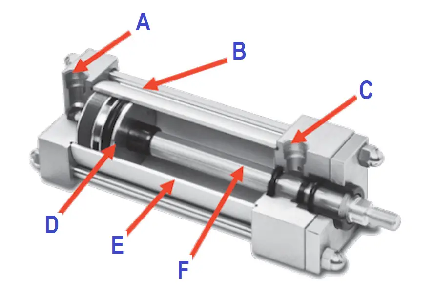
Image Courtesy: Tameson
- Cap-end port (A),
- Tie rod (B),
- Rod-end port (C),
- Piston (D),
- Barrel (E), and
- Piston rod (F)
Pneumatic cylinders can be used for pressure ranges between 5 bar to 20 bar.
Principle
The pneumatic cylinder converts the pressure energy of a compressed air medium into mechanical energy in the form of linear or rotary motion.
Single Acting Cylinder
Only one side of the piston is supplied with certain working pressure. Force acts in one direction to control the movement, returns to normal state by an external force such as a spring inside.
Types of Single Acting Cylinders
Based on the operation the Single-acting cylinders are classified as
- Push type and
- Pull type.
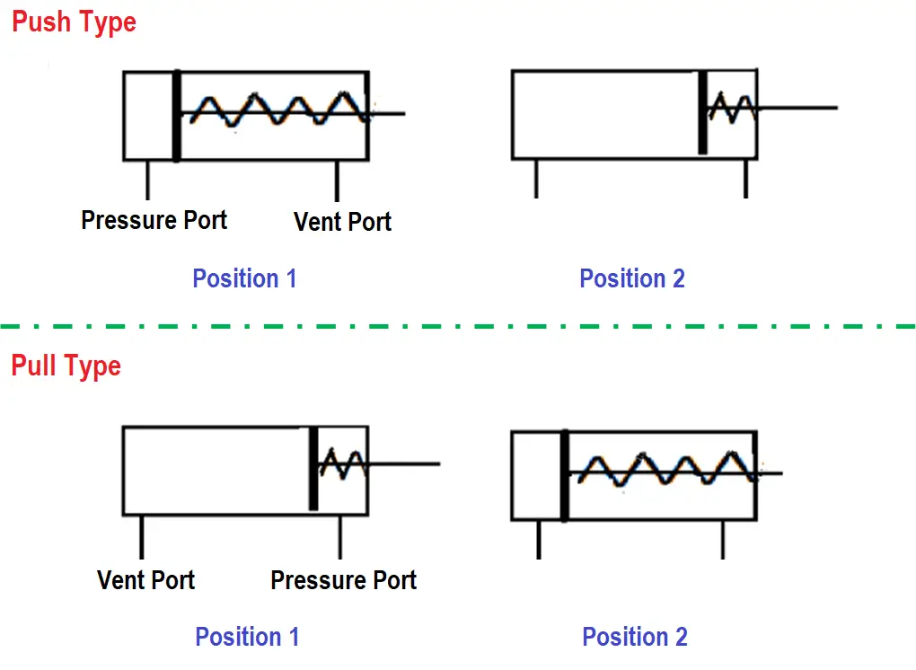
Push type Single-acting Cylinder
Compressed air enters to push the piston out of the cylinder. The spring automatically retracts the piston to its home position when the pressure is removed.
Pull type Single-acting Cylinder
Compressed air enters to pull the piston inside of the cylinder. When the compressed air passed through the port, the piston in the cylinder starts retracting. The pressure port is located at the cylinder end.
Double Acting Cylinder
Both sides of the cylinder are supplied with certain working pressure. Force exerted by the compressed air moves the cylinder piston rod in two directions.
Telescopic Cylinder
Both single acting and double acting cylinders are available in Telescopic type but widely used in hydraulic applications in high load handling. Such as heavy cranes, dumpers, etc., Pneumatic Telescopic cylinders are rarely used, not discussed more in detail in this article.
- Tie rod cylinder
- Flanged type
- One-piece welded
- Threaded end
Tie rod Cylinder
Tie rods are used for all types of cylinders irrespective of loads- heavy-duty, medium-duty, and low duty loads.
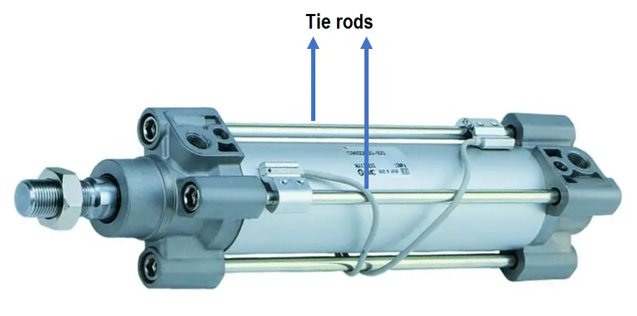
Image Courtesy: Thorite
Where there is a possibility of impact load or shock load coming on to the cylinder, the tie rods have been found to protect the cylinders from damages better than the other designs.
Flanged Type
They are heavy-duty cylinders similar to tie rod construction.
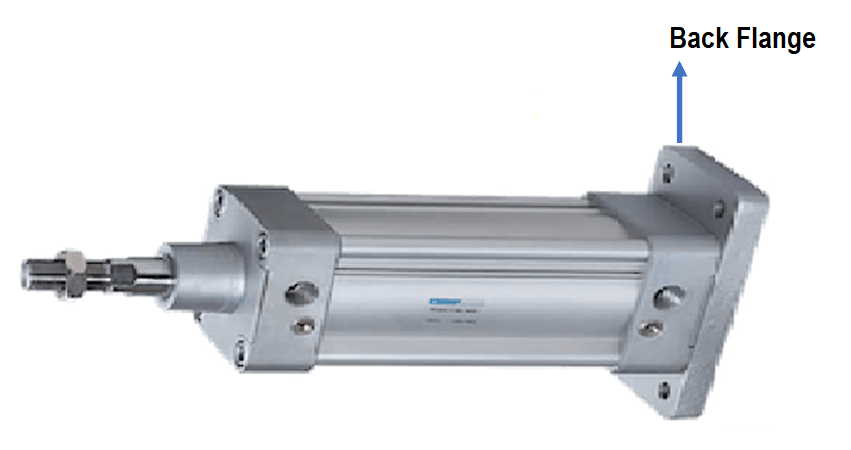
Image Courtesy: Parker Cylinders
Front flanged, back flanged, or both front and back flanged can be ordered from the manufacturer depending on necessity.
One-piece Welded
In this type, the body is cast integrally or the ends are welded or crimped.
Threaded End
In this type of construction, both the ends are screwed on to the tube by threading outside or inside.
Double-acting Cylinders
According to the operational principle, the double-acting cylinders are
- Through rod Cylinder
- Cushion end Cylinder
- Tandem Cylinder
- Impact Cylinder
- Cable Cylinder
- Rotary or turn cylinder
Through rod Cylinder
In this case, the piston rod is extended on both ends of the piston. This will make sure equal force and speed on both sides of the cylinder.
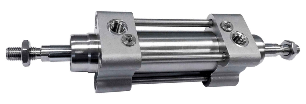
Image Courtesy: Aignep
Cushion End Cylinder
In this case, the piston has a cushioned nose at one or both ends of the piston for gradual deceleration of position near the ends of the stroke.
Cushioning may be of rubber buffers to absorb shock and to prevent the impact of the piston on end covers can be avoided.
Tandem Cylinder
In this case, two cylinders are arranged in series so that the force obtained from the cylinder becomes double.
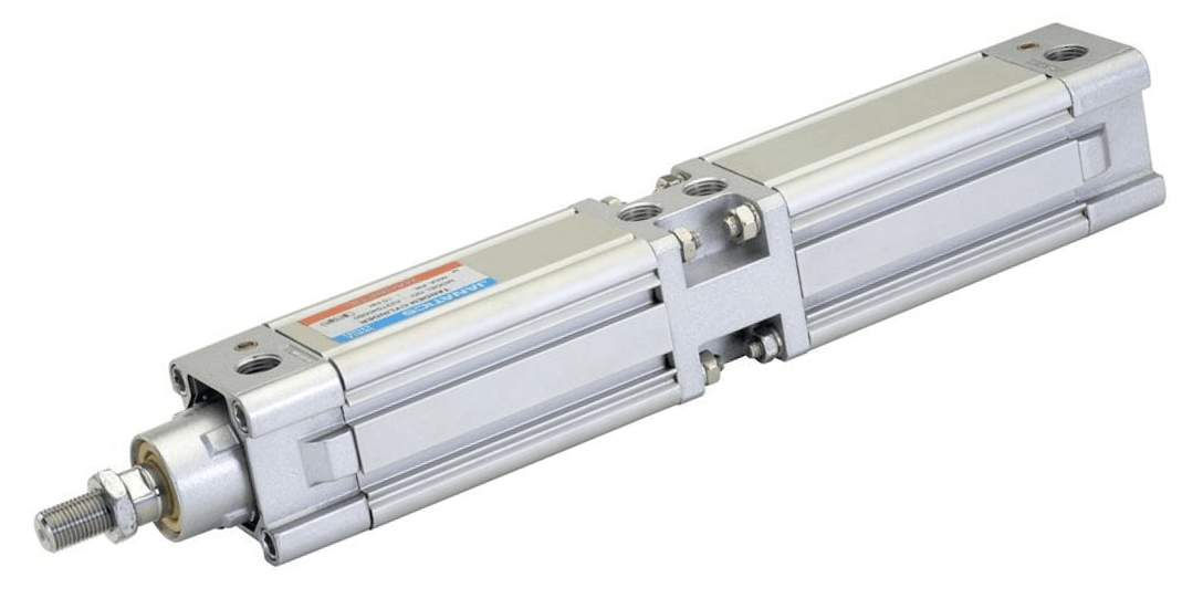
Image Courtesy: Janatics
Impact Cylinder
In this case, the piston rod of the cylinder is specially designed for accelerating high force or impact.
Cable Cylinder
In this case, a cable is attached on both ends of the cylinder eliminating the piston rod. This is called a rodless cylinder also. Cable-type cylinders are used in applications requiring long strokes.
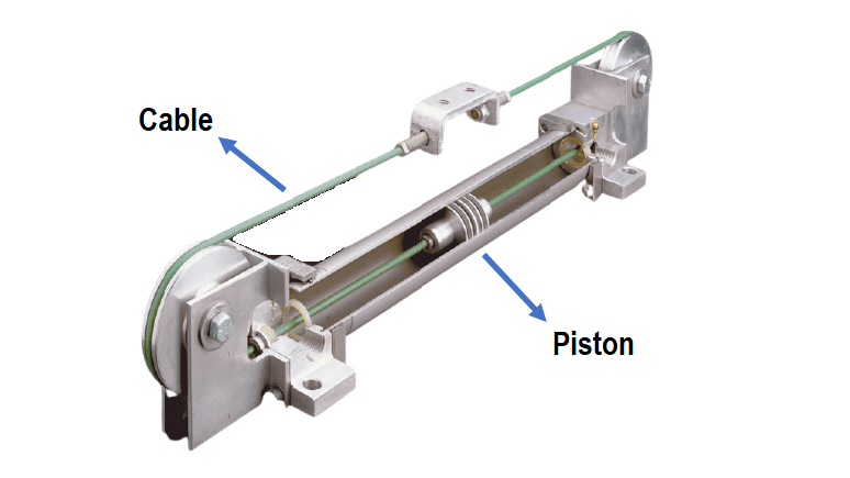
Image Courtesy: hydraulicspneumatics
The benefit of this is
- Space-saving when installing the cylinder.
- Relatively low cost per inch of stroke.
Rotary or Turn Cylinder
In this case, the piston rod having a rotary profile against a worm wheel and provides a linear movement.
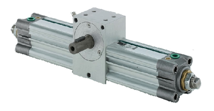
Image Courtesy: Janatics
Cylinder Specifications
Following are a few specifications to be checked while ordering a pneumatic cylinder.
- Cylinder Bore
- Piston rod diameter
- stroke length
- mounting style
- pressure range
- force output at maximum pressure
- Cushioning (at one end or both the ends of cylinder)
- Standard operating temperature
Applications
The SINGLE acting cylinders are used for simple applications.
DOUBLE acting cylinders are used for complex and heavy load applications.
SINGLE acting cylinder generates a force in only one direction.
DOUBLE acting cylinders are used where high force is required in both directions.
Resources:
- 1.Industrial Control Technology by Peng Zhang.
- Fluid Power Dynamics by R.Keith Mobley.
- Industrial Hydraulics, Pneumatics by Purushottam Balaso Pawar.
Read Next:
- Industrial Automation Systems
- What is a Fire Alarm System?
- Project Planning DCS System
- Functions and Parts of PLC
- What is Mimic Panel?