PLC Programming LED Control
Design a PLC ladder logic for the following application.
We are using three toggle Switches to control three LED’s
- If Toggle Switch 1 and Toggle Switch 2 are ON, then LED 1 and LED 2 will be ON.
- If Toggle Switch 2 and Toggle Switch 3 are ON, then LED 2 will be OFF, and LED 3 will be ON.
Digital Inputs
The required inputs are listed below.
Toggle Switch 1: I0.0
Toggle Switch 2: I0.1
Toggle Switch 2: I0.1
Here we call these toogle switches as simple “Switch” in our next discussions, But remember these are toggle-type switches.
Digital Inputs
The required outputs are listed below.
LED 1: Q0.0
LED 2: Q0.1
LED 3: Q0.2
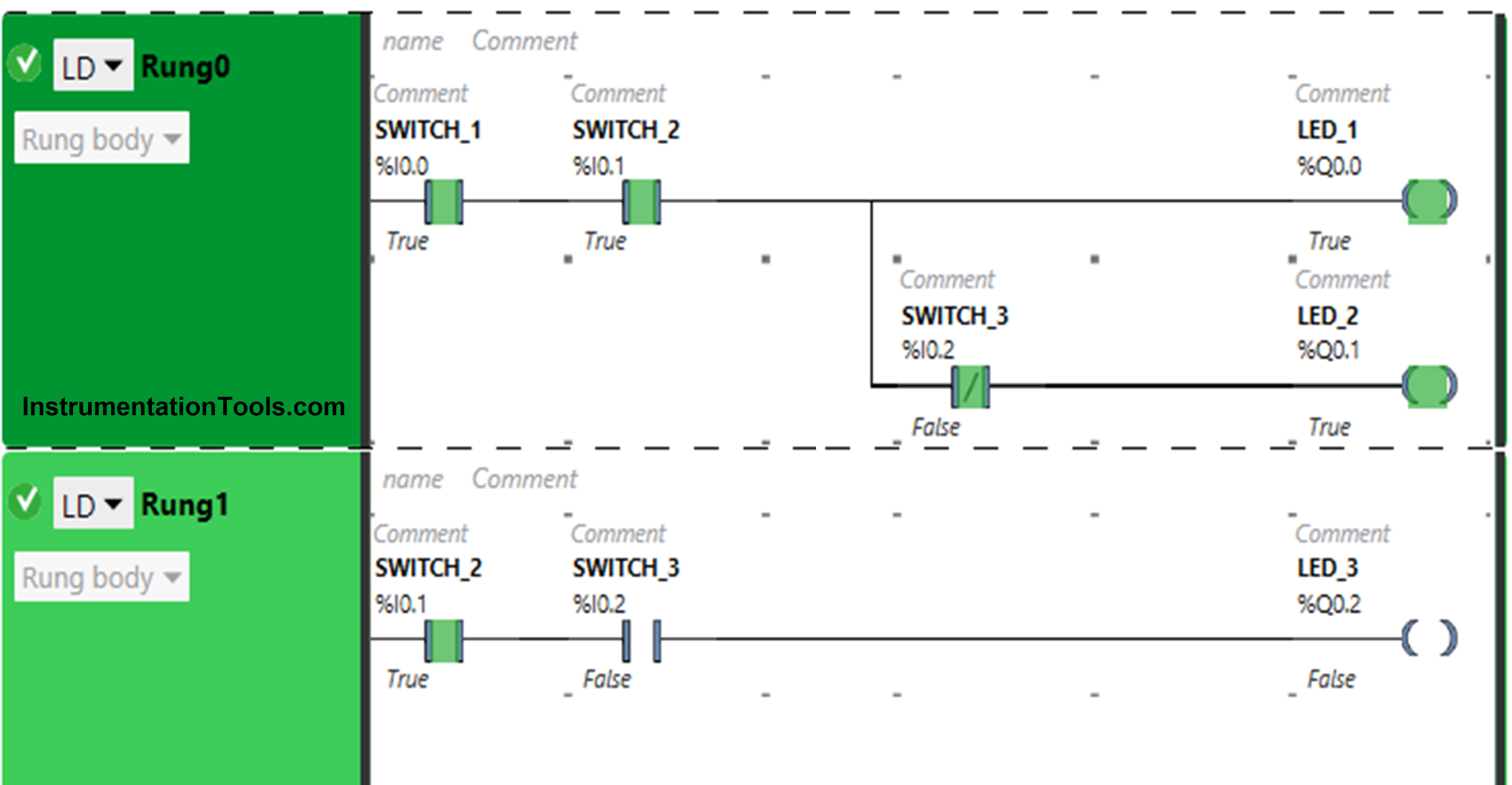
Ladder Diagram for LED Control
PLC Program Description
- For this application, we used EcoStruxure Machine Expert Basic v1.2 software for programming.
- In the above program, we have used Normally Open Contacts for Switch 1 (I0.0), Switch 2(I0.1), and Switch 3 (I0.2). We have also used Normally Closed Contact for Switch 3 (I0.2).
- Switch 1 and Switch 2, present in Rung0 are connected in series for LED 1 and LED 2, thus implementing AND logic gate.
- With Switch 1 and Switch 2, Switch 3 is connected to LED 3 as Normally Closed Contact.
- For LED 3, Switch 2 and Switch 3 present in Rung1 are connected in series, thus implementing the AND logic gate.
- For LED 1 to be ON, Switch 1 and Switch 2 should be ON.
- When Switch 1 and Switch 2 are turned ON and Switch 3 is OFF, then LED 2 will be ON.
- When Switch 2 and Switch 3 are ON, LED 3 will be ON.
- Turning ON Switch 3 will turn OFF LED 2.
When Switch 1 and Switch 2 are ON
In Rung0, the signal through Switch 1 and Switch 2 when turned ON.
As a result, LED 1 and LED 3 will turn ON. Switch 3 is used as a Normally Closed Contact for Switch 3 when in a false state, it will allow the signal to turn ON LED 2.
When Switch 2 and Switch 3 are ON
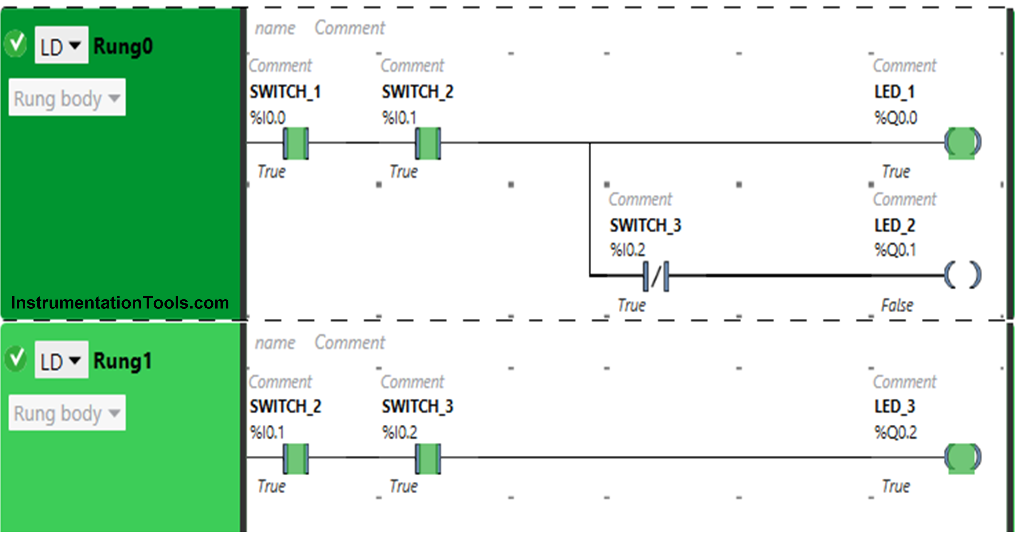
The signal through Switch 2 and Switch 3 in Rung1, that turns ON LED 3.
In Rung0, switch 3 is taken as Normally Closed Contact, when in the true state, it will not allow signal to pass through it. As a result, LED 2 will turn OFF. Switch 3 is connected to LED 1 and therefore, it will remain ON.
PLC Tutorial Video
You can also watch the tutorial video below for this LED control PLC example program.
If you liked this article, then please subscribe to our YouTube Channel for PLC and SCADA video tutorials.
You can also follow us on Facebook and Twitter to receive daily updates.
Read Next:
- PLC Objective Questions
- True or False PLC Quiz
- PLC Multiple Choice Questions
- Troubleshooting PLC
- PLC Animation