Inst ToolsInst ToolsInst Tools
  • Courses
  • Automation
    • PLC
    • Control System
    • Safety System
    • Communication
    • Fire & Gas System
  • Instrumentation
    • Design
    • Pressure
    • Temperature
    • Flow
    • Level
    • Vibration
    • Analyzer
    • Control Valve
    • Switch
    • Calibration
    • Erection & Commissioning
  • Interview
    • Instrumentation
    • Electrical
    • Electronics
    • Practical
  • Q&A
    • Instrumentation
    • Control System
    • Electrical
    • Electronics
    • Analog Electronics
    • Digital Electronics
    • Power Electronics
    • Microprocessor
  • Request
Search
  • Books
  • Software
  • Projects
  • Process
  • Tools
  • Basics
  • Formula
  • Power Plant
  • Root Cause Analysis
  • Electrical Basics
  • Animation
  • Standards
  • 4-20 mA Course
  • Siemens PLC Course
Reading: How Pilot operated Solenoid Valve Works ?
Share
Font ResizerAa
Inst ToolsInst Tools
Font ResizerAa
  • Courses
  • Design
  • PLC
  • Interview
  • Control System
Search
  • Courses
  • Automation
    • PLC
    • Control System
    • Safety System
    • Communication
    • Fire & Gas System
  • Instrumentation
    • Design
    • Pressure
    • Temperature
    • Flow
    • Level
    • Vibration
    • Analyzer
    • Control Valve
    • Switch
    • Calibration
    • Erection & Commissioning
  • Interview
    • Instrumentation
    • Electrical
    • Electronics
    • Practical
  • Q&A
    • Instrumentation
    • Control System
    • Electrical
    • Electronics
    • Analog Electronics
    • Digital Electronics
    • Power Electronics
    • Microprocessor
  • Request
Follow US
All rights reserved. Reproduction in whole or in part without written permission is prohibited.
Inst Tools > Blog > Control Valves > How Pilot operated Solenoid Valve Works ?

How Pilot operated Solenoid Valve Works ?

Last updated: June 18, 2019 7:27 am
Editorial Staff
Control Valves Solenoid Valve
1 Comment
Share
4 Min Read
SHARE

Basics of Pilot Operated Solenoid Valves

Pilot operated Solenoid Valve Principle

A solenoid valve has two main parts: the solenoid and the valve. The solenoid converts electrical energy into mechanical energy which, in turn, opens or closes the valve mechanically.

A direct acting valve has only a small flow circuit, shown within section E of this diagram (this section is mentioned below as a pilot valve). In this example, a diaphragm piloted valve multiplies this small pilot flow, by using it to control the flow through a much larger orifice.

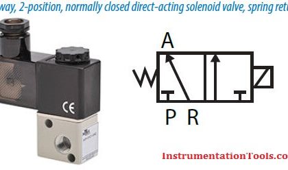
Solenoid valves may use metal seals or rubber seals, and may also have electrical interfaces to allow for easy control. A spring may be used to hold the valve opened (normally open) or closed (normally closed) while the valve is not activated.

Basics of Pilot Operated Solenoid Valves

A- Input side
B- Diaphragm
C- Pressure chamber
D- Pressure relief passage
E- Electro Mechanical Solenoid
F- Output side

The diagram to the right shows the design of a basic valve, controlling the flow of water in this example. At the top figure is the valve in its closed state. The water under pressure enters at A. B is an elastic diaphragm and above it is a weak spring pushing it down.

The diaphragm has a pinhole through its center which allows a very small amount of water to flow through it. This water fills the cavity C on the other side of the diaphragm so that pressure is equal on both sides of the diaphragm, however the compressed spring supplies a net downward force. The spring is weak and is only able to close the inlet because water pressure is equalized on both sides of the diaphragm.

Once the diaphragm closes the valve, the pressure on the outlet side of its bottom is reduced, and the greater pressure above holds it even more firmly closed. Thus, the spring is irrelevant to holding the valve closed.

The above all works because the small drain passage D was blocked by a pin which is the armature of the solenoid E and which is pushed down by a spring. If current is passed through the solenoid, the pin is withdrawn via magnetic force, and the water in chamber C drains out the passage D faster than the pinhole can refill it.

The pressure in chamber C drops and the incoming pressure lifts the diaphragm, thus opening the main valve. Water now flows directly from A to F.

When the solenoid is again deactivated and the passage D is closed again, the spring needs very little force to push the diaphragm down again and the main valve closes. In practice there is often no separate spring; the elastomer diaphragm is molded so that it functions as its own spring, preferring to be in the closed shape.

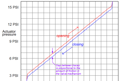
From this explanation it can be seen that this type of valve relies on a differential of pressure between input and output as the pressure at the input must always be greater than the pressure at the output for it to work. Should the pressure at the output, for any reason, rise above that of the input then the valve would open regardless of the state of the solenoid and pilot valve.

Don't Miss Our Updates
Be the first to get exclusive content straight to your email.
We promise not to spam you. You can unsubscribe at any time.
Invalid email address
You've successfully subscribed !

Continue Reading

What is a Pneumatic Cylinder?
What is a Electric Solenoid Actuator ?
What is Cage-guided Globe Valve ?
Basics of Actuators
Electrical Actuators
Types of Check Valves
Share This Article
Facebook Whatsapp Whatsapp LinkedIn Copy Link
Share
1 Comment
  • Hareef mohamed says:
    August 5, 2017 at 12:41 pm

    very useful site for instrument technicians

    Reply

Leave a Reply Cancel reply

Your email address will not be published. Required fields are marked *

Stay Connected

128.3kFollowersLike
69.1kFollowersFollow
210kSubscribersSubscribe
38kFollowersFollow

Categories

Explore More

Pressure Relief Valve Terminology
Short Notes on Different Valve Types
Valve Seat Leakage Test
SIS Final Control Elements
 Control Valve Accessories – Principle, Purpose, Advantages
What is Cavitation? What are the Causes?
Spring and Diaphragm Pneumatic Actuators
Safety Relief Valve Quiz: Test Your Knowledge

Keep Learning

Control Valves Basic Theory

Control Valves Theory

Free Online Control Valves Course

Free Control Valves Course

Control Valves Questions and Answers

Control Valve Questions and Answers

Flapper nozzle system

What is Flapper Nozzle System ?

Difference between BDV and PSV

Difference between BDV and PSV

gate-valve-principle-animation

Basics of Gate Valves

radial-vane damper

Dampers and Louvres

Full Bore or Reduced Bore Valves

When to choose Full Bore Valve or Reduced Bore Valve ?

Learn More

Basic DC Power Supply Circuit

Basic DC Power Supply Circuit

Electro Mechanical Systems Objective Questions

Electro Mechanical Systems Objective Questions

IS Loop Formula

Difference between Intrinsic Safe and Non-Intrinsic Safe Cables

Industrial Networking Interview Questions

Industrial Networking and Wireless Interview Questions

Ultrasonic Transmitters vs. Guided Wave Radar Transmitters

Ultrasonic Transmitters vs Guided Wave Radar for Level Measurement

Comparison of CB, CE & CC Amplifiers

Comparison of Transistor Configurations

Ladder Logic for Stair-Case wiring using Toggle Switches

Ladder Logic for Stair-Case wiring using Toggle Switches

Cyber Security Multiple Choice Questions and Answers

Cyber Security Multiple Choice Questions and Answers

Menu

  • About
  • Privacy Policy
  • Copyright

Quick Links

  • Learn PLC
  • Helping Hand
  • Part Time Job

YouTube Subscribe

Follow US
All rights reserved. Reproduction in whole or in part without written permission is prohibited.
Welcome Back!

Sign in to your account

Username or Email Address
Password

Lost your password?