Erection & Commissioning

P&ID Guidelines for Pressure Safety Valves

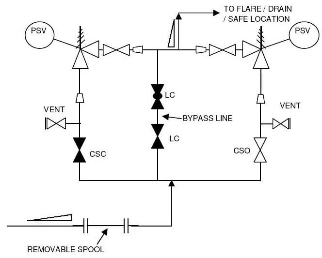
Typical P&ID arrangement – Pressure Safety Valves

P&ID arrangement for Pressure Safety Valves

  • The sample drawing presented here represents a typical arrangement generally used to represent safety valves or relief valves on P&ID. First of all a proper safety valve symbol should be selected to represent the control valve as per the project standards.
  • For protecting equipments that are not spared and equipments that cannot be isolated without disrupting the plant / unit a spare safety valve is recommended to be provided as shown in the sample drawing.
  • Generally, the safety valve inlet / outlet nozzles are smaller than the corresponding line sizes. This change in diameter should be clearly indicated in the P&ID with reducer and expander.
  • Block valves should be provided upstream and downstream of the safety valves in case of shutdown and maintenance. Normally provision is made to keep these valves locked or sealed open. The spare safety valve is kept locked or sealed closed, as indicated in the sample drawing.
  • A vent valve is normally provided between the safety valve and upstream block valve.
  • Normally, bypass should provided for safety valves for process or start-up requirements. Type, number and size of bypass valves will depend on the project standards.
  • Depending on the service handled, the discharge from PSV can be either routed to flare system for hydrocarbon service, for closed/open drain systems or to atmosphere at a safe location for non-hazardous service.
  • The inlet lines to the safety valves are always sloped toward to protected equipment and the outlet lines from the safety valves are always sloped towards the flare header / the knock out drum or the safe location.
  • When a PSV is connected to the flare system, the inlet line piping should be equipped with a spool piece to facilitate dismantling, as indicated in the sample drawing. For PSVs discharging to atmosphere, this is not required.
  • All the guidelines given here are very general and may be modified as per specific requirements of any particular project.
You've successfully subscribed !

View Comments

Share

Recent Articles

  • PLC Tutorials

VFD Simulator Download – Free Yaskawa V1000 Software

VFD simulator download: Master the online tool from the Yaskawa V1000 & programming software for…

2 days ago
  • PLC Tutorials

Conveyor Sorting Machine PLC Program with Calculation Function

The conveyor sorting machine is widely used in the packing industries using the PLC program…

5 days ago
  • PLC Tutorials

Example of Flip-Flop PLC Program for Lamps Application

Learn the example of flip-flop PLC program for lamps application using the ladder logic to…

5 days ago
  • PLC Tutorials

STAR DELTA Programming using PLC Controller

In this article, you will learn the STAR DELTA programming using PLC controller to start…

6 days ago
  • Instrumentation Design

Single and Three Phase Immersion Electrical Heaters Wiring Circuits

Lube oil consoles of rotary equipment packages in industrial process plants are usually equipped with…

3 days ago
  • Instrumentation Design

Immersion Heaters in Lube Oil Consoles

Rotating equipment packages such as pumps, compressors, turbines need the lube oil consoles for their…

5 days ago