A phototransistor is similar to a regular BJT except that the base current is produced and controlled by light instead of a voltage source. The phototransistor effectively converts light energy to an electrical signal.
In a phototransistor the base current is produced when light strikes the photosensitive semiconductor base region. The collector-base pn junction is exposed to incident light through a lens opening in the transistor package. When there is no incident light, there is only a small thermally generated collector-to-emitter leakage current, ICEO; this dark cur- rent is typically in the nA range. When light strikes the collector-base pn junction, a base current, Iλ, is produced that is directly proportional to the light intensity. This action produces a collector current that increases with Iλ. Except for the way base current is generated, the phototransistor behaves as a conventional BJT. In many cases, there is no electrical connection to the base.
The relationship between the collector current and the light-generated base current in a phototransistor is
Ic = βDCTλ
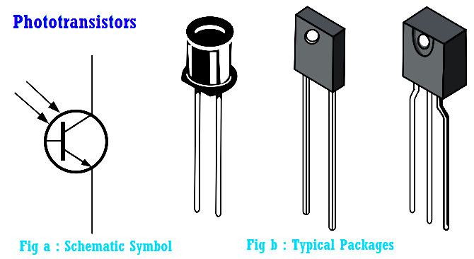
The schematic symbol and some typical phototransistors are shown in Below Figure.
Since the actual photogeneration of base current occurs in the collector-base region, the larger the physical area of this region, the more base current is generated. Thus, a typical phototransistor is designed to offer a large area to the incident light, as the simplified structure diagram in Below Figure illustrates.
A phototransistor can be either a two-lead or a three-lead device. In the three-lead configuration, the base lead is brought out so that the device can be used as a conventional BJT with or without the additional light-sensitivity feature. In the two-lead configuration, the base is not electrically available, and the device can be used only with light as the input. In many applications, the phototransistor is used in the two-lead version.
Below Figure shows a phototransistor with a biasing circuit and typical collector characteristic curves. Notice that each individual curve on the graph corresponds to a certain value of light intensity (in this case, the units are mW/cm2) and that the collector current in creases with light intensity.
Phototransistors are not sensitive to all light but only to light within a certain range of wavelengths. They are most sensitive to particular wavelengths in the red and infrared part of the spectrum.
This PLC example on manufacturing line assembly is an intermediate-level PLC program prepared for the…
In this article, you will learn the PLC programming example with pushbutton and motor control…
This article teaches how to convert Boolean logic to PLC programming ladder logic with the…
In this article, you will learn the PLC programming example on timers function block using…
Design a program for PLC pump control such that the pump must be turned ON…
Polyvinyl alcohol (PVA) is a water-soluble and biodegradable synthetic polymer used in oil field cementing…


