A LED that emits one colour when forward biased and another colour when reverse biased is called a multicolour LED.
One commonly used schematic symbol for these LEDs is shown in below figure.
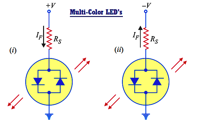
Multi Color LED’s actually contain two pn junctions that are connected in reverse-parallel i.e. they are in parallel with anode of one being connected to the cathode of the other.
If positive potential is applied to the top terminal as shown in Fig. (i), the pn junction on the left will light. Note that the device current passes through the left pn junction.
If the polarity of the voltage source is reversed as shown in Fig. (ii), the pn junction on the right will light. Note that the direction of device current has reversed and is now passing through the right pn junction.
Multicolour LEDs are typically red when biased in one direction and green when biased in the other. If a multicolour LED is switched fast enough between two polarities, the LED will produce a third colour.
A red/green LED will produce a yellow light when rapidly switched back and forth between biasing polarities.
Learn an example PLC program to control a pump based on level sensors using ladder…
In the PLC timer application for security camera recording, when motion is detected then camera…
In this example, we will learn batch mixing with PLC ladder logic program using timer…
This PLC example on manufacturing line assembly is an intermediate-level PLC program prepared for the…
In this article, you will learn the PLC programming example with pushbutton and motor control…
This article teaches how to convert Boolean logic to PLC programming ladder logic with the…
