Inst ToolsInst ToolsInst Tools
  • Ask
  • Courses
  • Videos
  • Q & A
    • Interview
      • Instrumentation
      • Electronics
      • Electrical
      • Practical Questions
    • MCQ
      • Instrumentation MCQ
      • Electrical MCQ
      • Electronics MCQ
      • Control Systems MCQ
      • Analog Electronics MCQ
      • Digital Electronics MCQ
      • Power Electronics MCQ
      • Microprocessor MCQ
      • Multiple Choice Questions
  • EE
    • Electronics
      • Electronics Q & A
      • Electronic Basics
      • Electronic Devices & Circuits
      • Electronics Animation
      • Digital Electronics
    • Electrical
      • Electrical Basics
      • Electrical Q & A
      • Power Electronics
      • Electrical Machines
      • Electrical Animation
      • Power Systems
      • Switchgear & Protection
      • Transmission & Distribution
  • Measure
    • Control Valves
    • Calibration
    • Temperature
    • Pressure
    • Flow
    • Level
    • Analyzers
    • Switches
    • Vibration
    • Solenoid Valve
  • Control
    • PLC Tutorials
    • Control Systems
    • Safety Instrumented System (SIS)
    • Communication
    • Fire & Gas System
  • More
    • Design
    • Tools
    • Animation
    • Basics
    • Formulas
    • Standards
    • TextBooks
    • Common
    • Software
    • Excel Tools
    • Erection & Commissioning
    • Process Fundamentals
    • Videos
    • Books
Search
All rights reserved. Reproduction in whole or in part without written permission is prohibited.
Reading: Impulse Piping standards for Field instruments
Share
Notification Show More
Font ResizerAa
Inst ToolsInst Tools
Font ResizerAa
  • Courses
  • PLC Tutorials
  • Control Systems
Search
  • Ask
  • Courses
  • Videos
  • Q & A
    • Interview
    • MCQ
  • EE
    • Electronics
    • Electrical
  • Measure
    • Control Valves
    • Calibration
    • Temperature
    • Pressure
    • Flow
    • Level
    • Analyzers
    • Switches
    • Vibration
    • Solenoid Valve
  • Control
    • PLC Tutorials
    • Control Systems
    • Safety Instrumented System (SIS)
    • Communication
    • Fire & Gas System
  • More
    • Design
    • Tools
    • Animation
    • Basics
    • Formulas
    • Standards
    • TextBooks
    • Common
    • Software
    • Excel Tools
    • Erection & Commissioning
    • Process Fundamentals
    • Videos
    • Books
Follow US
All rights reserved. Reproduction in whole or in part without written permission is prohibited.
Inst Tools > Blog > Basics > Impulse Piping standards for Field instruments

Impulse Piping standards for Field instruments

Last updated: April 2, 2019 7:03 pm
Editorial Staff
Basics Pressure Measurement
6 Comments
Share
2 Min Read
SHARE

What is Impulse Piping?

The impulse piping is the one which connects the process outputs to the transmitter.

Contents
What is Impulse Piping?Differential Pressure Transmitters Hook up1. Liquid2. Gas3. SteamSummary :Liquid lines :Gas Service :Steam Service :

Impulse Piping standards for Field instruments

It must convey the process pressure accurately. If for example, the gas collects in a liquid-filled impulse line, or the drain of a gas-filled impulse line becomes plugged, it will not convey the pressure accurately.

Since this will cause errors in measurement output, selecting the proper piping method for the process fluid (gas, liquid or steam) is very important. We discuss below some of the most common routing principles for impulse piping.

Differential Pressure Transmitters Hook up

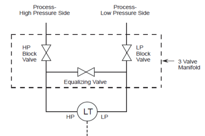
In differential pressure transmitters, there is a chance that process fluid (liquid, gas or vapors) may accumulate inside the impulse piping that can cause inaccurate reading of pressures.

There are three cases as depicted by the figure.

1. Liquid

If the process fluid is liquid, the transmitter should be placed lower than the taps.

2. Gas

If the process fluid is gas, the transmitter should be placed higher than the taps.

3. Steam

If the process fluid is steam, it has more chances to vaporize, so we should use condensate pot and the transmitter should be placed at lower level than the taps.

Impulse Piping Connections

DP Transmitters for Open Tank-Closed Tank

Process Piping Connections

Summary :

Liquid lines :

On liquid lines the transmitter is mounted below the orifice plate because liquids have a property of self draining.

Gas Service :

On gas service the transmitter is mounted above the orifice plate because Gases have a property of self venting and secondly condensate formation.

Steam Service :

On steam service the transmitter is mounted below the orifice plate with condensate pots. The pots should be at the same level.

piping for a Different pressure flow transmitter

Don't Miss Our Updates
Be the first to get exclusive content straight to your email.
We promise not to spam you. You can unsubscribe at any time.
Invalid email address
You've successfully subscribed !
What is the Difference Between Sensor and Transducer?
Pressure Gauges with Bourdon Tube Principle
Well Manometer Principle
Pressure Gauge Problems
Pressure Transmitter Manifolds
Share This Article
Facebook Whatsapp Whatsapp LinkedIn Copy Link
Share
6 Comments
  • mubin yuwana says:
    October 31, 2016 at 1:07 pm

    thank you sir it was very helpful for me , i am waiting for the next lesson

    Reply
  • Clayton Gonsalves says:
    March 13, 2019 at 9:06 pm

    I’m not sure how active the administrator is on this site, but I’m looking for recommendations about situations where customer requirements are not permitting transmitters to be placed below the tap location.

    This is because the customer requires that the transmitters be supported by stanchions, and the stanchions must be taller than 0.6 meters.

    The pipeline being sensed is sitting at 0.5 meters, so I’m wondering what possible solutions I can consider.

    Reply
    • Vijith Vijith says:
      March 20, 2024 at 2:38 pm

      If the service is liquid, transmitter to be located meter below the tapping point because liquid has a property or tendency to self draining.

      Reply
  • Raghava S Chari says:
    September 20, 2021 at 4:18 am

    Inst Tools notes on impulse lines – process leads is better term in my opinion – to steam flow transmitters show condensate pots. These were necessary to reduce flow measurements temporary errors from the by gone days used high volumetric displacement mercury fill float manometers type flow meters during rapid flow changes.

    On the other hand present day DPTs volumetric displacement is zero and hence no temporary errors during rapid flow fluctuations. Not providing the condensate pots benefits are:

    Enormous Cost Savings by providing a not required expensive item
    Far fewer likely leaks fittings

    Reply
  • Raghava S Chari says:
    September 24, 2021 at 1:11 pm

    For Clayton Gonsalves

    I too firmly believe that liquid and steam measuring instruments should be below the pipelines even if the pipe runs on the floor. One way of complying is dig a 2x2x2m pit with 0.35m tall rain water prevention wall above ground level. Cement the entire pit. Crew should drain the liquid into a bucket and dispose it outside.

    A red painted chain barricade prevents persons accidentally falling into the pit. I have done it for a 220-bars liquid ammonia flow DPT. As the liquid NH3 is very pungent I clamped a hose well to the drain to prevent hose pull outs and left the other end in a top full open (No disc) 200 liter barrel 3/4 water fill placed on the ground.

    Clamped the hose to the barrel to prevent whips. The drained liquid NH3 instantly evaporates; but being highly water soluble it dissolves in the water. Take the operators’ help to dispose off the collection.

    Reply
  • Tushar says:
    December 2, 2022 at 9:33 am

    Why instrument impulse tube pressure rating is higher than that of pipe pressure rating i.e. 1500# or more?

    Reply

Leave a Reply Cancel reply

Your email address will not be published. Required fields are marked *

Stay Connected

128.3kFollowersLike
69.1kFollowersFollow
208kSubscribersSubscribe
38kFollowersFollow

Categories

Recent Comments

  • Guifty Shimica on Top Non-PLC Certification Courses for Automation Professionals
  • Guifty Shimica on Top Non-PLC Certification Courses for Automation Professionals
  • MIHARITSOA Aina Sitraka on Top Non-PLC Certification Courses for Automation Professionals
  • Vaishnavi on Free Instrumentation Course for Trainee Engineers

Related Articles

Instrumentation Symbols Legend

Instrumentation Symbols Legend

Why 4-20 mA Current Signal is used instead of Voltage Signal

Troubleshooting a 4-20mA Current loop

Remote Diaphragm Seal Transmitter for Vacuum Application

Remote Diaphragm Seal Transmitter for Vacuum Application

4-20mA Current Loop

Basics of 4-20mA Current Loop

Pressure gauge mechanism

How Measurement Span of Pressure Gauge Could be Changed?

What Every Instrument Engineer Should Know

Common Mistakes in Instrumentation

Bellow Principle

Bellows

Transmitters 4-20mA Current Failure Alarm Limits

Transmitters 4-20mA Current Failure Alarm Limits

More Articles

Nuclear Level Measurement

Nuclear Level Detectors Cascade or Master/Slave concept

PID Loop Tuning

PID Controller Loop Tuning Questions and Answers – Part 1

Monsoon Protection for Field Instruments and Junction Boxes

Monsoon Protection for Field Instruments and Junction Boxes

Calibration Procedure of displacer type Level transmitter

Calibration of Displacer Level Transmitter

Four Wire RTD Circuit

What is a Four-wire RTD ?

Flow meter Turndown Ratio

Importance of Flow Meter Turndown Ratio

Zigbee Projects

Zigbee Based Project Ideas and List

Reasons to Calibrate Flowmeters

Reasons to Calibrate Different Types of Flow Meters

Follow US
All rights reserved. Reproduction in whole or in part without written permission is prohibited.
Welcome Back!

Sign in to your account

Username or Email Address
Password

Lost your password?