How to calculate the inch or mmWC range of the level transmitter and explain with different examples.
We need to configure the Lower Range Value (LRV) and Upper Range Value (URV) for the level transmitters after installation in the field. The formula to calculate the LRV (4mA) and URV (20mA) will always change based on the transmitter mounting or installation position.
The below example shows the different types of level transmitters installation.
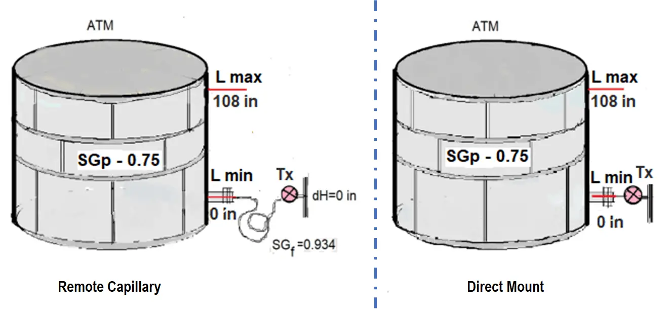
Tank span = Lmax *SGp – Lmin *SGp
Tank span = (108 in.* 0.75) – (0 in.* 0.75) = 81 inH2O
4 mA = Lmin *SGp + dH *SGf
4 mA = (0 in. 0.75) + (0 in.* 0.934) = 0 inH2O
20 mA = Lmax* SGp + dH * SGf
20 mA = (108 in.* 0.75) + (0 in.* 0.934) = 81 inH2O
Span = 81 inH2O (81 to 0 inH2O)
Note: Both installations would have the same calculated range points.
Note: Silicone 200 has a specific gravity of 0.934.
Tank span = Lmax* SGp – Lmin * SGp
Tan span = (108 in.* 0.75) – (0 in*. 0.75) = 81 inH2O
4 mA = Lmin *SGp + (dH* SGf)
4 mA = (0 in.* 0.75) + (60 in.* 0.934) = 56.04 inH2O
20 mA = Lmax *SGp + (dH *SGf)
20 mA = (108 in* 0.75) + (56.04* inH2O) = 137.04 inH2O
Span = 81 inH2O (137.04 to 56.04 inH2O)
Note: Silicone 200 has a specific gravity of 0.934.
Tank span = Lmax SGp – Lmin SGp
Tank span = (108 in. 0.75) = 81 inH2O
4 mA = Lmin * SGp +(dH * SGf)
4 mA = (0 in * 0.75) + (–120 in *. 0.934) = –112.08 inH2O
20 mA = Lmax * SGp + (dH* SGf)
20 mA = (108 in * 0.75) + (–120 in.* 0.934) = –31.08 inH2O
Span = 81 inH2O (–112.08 to –31.08 inH2O)
Note The height of the transmitter (Hd Sg) should not be greater than approximately 394 inH2O (14.2 PSI) not to exceed the 0.5 PSIA sensor limits of a coplanar DP or GP.
Tank span = Lmax SG
Tank span = 108 in. 0.75 = 81 inH2O
4 mA = Lmin *SGp – (dL* SGF) +(dH * SGf)
4 mA = (0 in. 0.75) – (60 in.* 0.934) + (– 60 in.* 0.934) = –112.08 inH2O
20 mA = Lmax * SGp – (dL * SGf) +(dH SGf)
20 mA = (108 in. 0.75) – (60 in. 0.934) + (–60 in. 0.934) = –31.08 inH2O
Span = 81 inH2O (–112.08 to –31.08 inH2O)
Note: Silicone 200 has a specific gravity of 0.934.
Tank span = Lmax *SGp – Lmin *SGp
Tank span = (108 in.* 0.75) = 81 inH2O
4 mA = Lmin *SGp – (dL*SGf)
4 mA = (0 in.* 0.75) – (120 in.* 0.934) = –112.08 inH2O
20 mA = Lmax *SGp – (dL* SGf)
20 mA = (108 in.* 0.75) – (120 in.* 0.934) = –31.08 inH2O
Span = 81 inH2O (–112.08 to –31.08 inH2O)
Note: Silicone 200 has a specific gravity of 0.934.
Source: manual-rosemount-dp-level-transmitters
Read Next:
A Real-Time Clock accurately tracks time from seconds to years and stores the data in…
Omron PLC logic for sorting the number of products and counting the number of products…
Learn the water fountain control logic using the PLC timers programming to control the high…
Open Telemetry is a framework for collecting data in cloud-native applications including tracing, metrics, and…
This article is about controlling the Pneumatic cylinder and Pneumatic motor in the assembly line…
In this post, we will learn the basic requirements for a network switch to be…


View Comments
Why does Tank span = (180 in.* 0.75) – (0 in*. 0.75) = 81 inH2O? as far as I can tell, 180*0.75 = 135? What's going on here that am I missing?
This is very Good and practically Hope I find a lot of engineering that can this tools help them
I'm in Concord with the initial commentor,My line of understanding that calculation,is blurry,won't some light be shed?.I'm talking about what DN is commenting about
i think the Lmax is 108 not 180..
Not thinking
Here in the examples all 180 are ,misplaced actually it was 108
And in 3rd example dh & dl are also wrong position according to theory
May this calculation will be correct by author
I thank everyone for their comments on the mistakes. Corrections have been done and updated in the article. I also thank Mr. Bharadwaj Reddy Garu for bringing various comments to my notice.
I need to know the minimum pipe size in high side used to measure fuel tank level in order not to cause Blockage due to rust dirty in fuel
Please why use of silicon 200 specific gravity