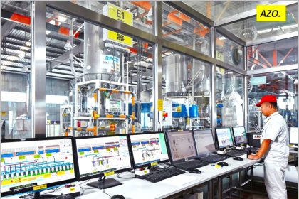
Industrial process control is everywhere. Sometimes it is dangerous or complex. In other cases it may be relatively mundane. In all industrial processes, though, maintaining operation is key. Stakeholders rely on the process output and look to the designers, engineers, and operators to deliver, in many cases, uninterrupted performance. The world is a place of many uncertainties, some of which can impact your process in undesirable ways. While it’s not practical to design or build to accommodate every possible adverse event, application of experience and good judgement in a few areas may significantly shorten the list of things that can negatively impact your process.
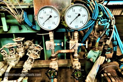
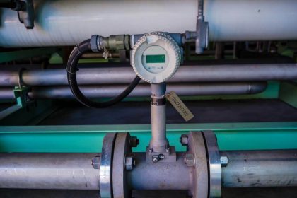
Process control is achieved through the measurement of various conditions and application of regulated adjustments to the process inputs to deliver a desired output. Process variable measurement serves as the input to the control system. In the industrial sphere, it is common to see devices used for the measurement and transmission of temperature, pressure, flow, mass, level, and electrical parameters like voltage, current, capacitance and more. Regardless of what is being measured, there are three common characteristics:
- Device – A combination of a sensor and a translator that together detect some physical condition of the process and produce an output signal that can be correlated to the process condition.
- Location – The device will have a location that is dictated by the process construction and arrangement. Device locations have a tendency to be inflexible.
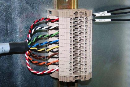
- Signal transmission path – Unless the control element is integral to, or adjacent to, the measurement device, there will be some path over which the measurement signal must travel to reach an associated control element.
Looking at these three elements for each measurement point, consider the five risk categories below in evaluating what you can do to safeguard your process measurement instrumentation. It’s advisable to open a conversation with an experienced application specialist and freely discuss your concerns. Gathering additional input from various experienced sources will help you determine how extensive your protective measures should be to deliver a balance between cost and the probability of certain adverse events.
- Local Weather: There is local weather data available for almost every place on the planet. Take the time to procure reliable data and examine the distribution of temperature, humidity, precipitation, and wind conditions throughout all seasons. Clearly, if portions of the process are located outdoors, extreme local weather conditions will need to be accommodated. Even if your process is located indoors, local weather information is important if the process is to operate continuously. Consider whether an indoor process must continue to operate, even if the building HVAC system fails and indoor conditions begin to be impacted by outdoor conditions. Also, depending upon the design of the building climate control system, changing outdoor conditions can have a noticeable and possibly significant impact on the indoor air conditions.
- Process Generated Conditions: There may be specific aspects of your process that produce occurrences of vibration, pressure spike, electrical interference, or a host of other aberrations that may affect the proper operation of measurement devices. Know your process….really know it. Protect instrument sensors from potentially damaging transients and other process conditions that can be reasonably expected to occur. Device location relative to sources of electrical interference, elevated temperature, vibration, shock, and other transient conditions should be considered.
- Security: Your design goal should be to achieve a very high level of certainty that the signals generated by the measurement devices are uninterrupted and reflect the actual process conditions. There are two cases I always consider for security. The first is cyber, which applies in the case of a process measurement device network connection. Necessary steps should be taken to thwart an attempt to breach the network and detect unusual conditions that might indicate an invader’s attempt to manipulate the process. My second case is related to device access by those without proper knowledge, training, or permission. Protection from these threats will likely involve a combination of physical barriers and procedures.
- Physical Contact: Industrial settings are, well, industrial. Large, heavy, irregular, unwieldy, and sharp things can sometimes be moved through areas occupied by process measurement gear. Technicians with carts, tools, and materials frequently pass through process areas to do their work. Protecting equipment and instruments from damaging contact pays dividends for the life of the installation. Consider, in your design and layout, the proximity of instruments to areas of traffic. If applicable, also consider areas overhead. The level of protection will need to be balanced with the need for access by qualified individuals for service, maintenance, calibration, and observation, as applicable.
- Moisture: Electronics are a mainstay of modern measurement instrumentation. Clearly, liquid moisture must be kept from contact with electronic circuits. Vaporous moisture will find a path to the internals of your electronic devices. This vapor, which is present in considerable levels in almost every indoor and outdoor environment, can condense when the right conditions are present. It is imperative that enclosures, conduit, boxes, fittings must be provided with barriers to moisture entry and/or a reliable means to automatically discharge accumulated liquid moisture before damage occurs.
