In electrical circuits, voltage is always measured between two points: a point of high potential and a point of low or zero potential.
The term “reference point” denotes the point of low potential because it is the point to which the voltage is referenced.
An example of a voltage measurement is shown in Figure 1.
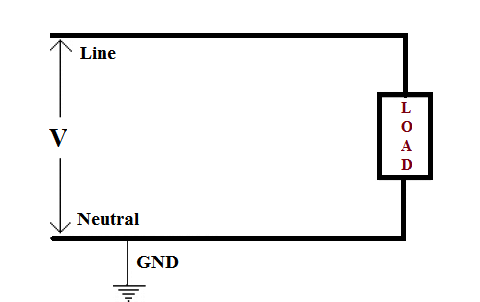
Figure 1: Voltage measurement between line (high) and neutral (low) with the neutral tied to a ground reference point
The voltage at the low reference point is often referred to as a “ground” or “earth ground” because it is tied directly to the earth.
Grounding electrical circuits is necessary for safety in the event that a fault occurs within the system.
Without a good ground, there could be potential shock hazards on any piece of electronic equipment.
Grounded systems can present their own set of problems. Small differences in potential within a grounding system can cause ground loops and these loops can have adverse effects ranging from data loss to presenting a severe safety hazard.
As a result, it is beneficial to utilize a power source that gives the operator the flexibility of choosing either a grounded or floating output reference.
Earth Ground and Chassis Ground
Earth and Ground are perhaps the most misunderstood terms in electronics.
The difference comes down to a matter of qualifying a reference point. The term “earth” literally indicates a reference point to planet earth.
The planet earth is essentially an infinite reservoir of electrons and thus the best place to “drain” excess electrons from a system.
The point of contact with earth reference is generally achieved by driving a conductive spike several feet into the ground, ensuring a solid earth connection.
Thus the term “earth ground” denotes a connection to an actual earth reference point (see Figure 2).
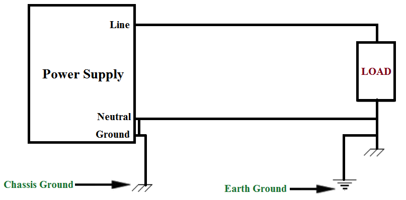
Figure 2: The “ground” point on the power supply is a chassis ground while the load has an earth ground reference.
The term “chassis ground” (Figure 2) indicates a ground reference on the dead metal enclosure points of an electronic device.
It is possible for this ground reference to sit at earth potential or at some other value if it is not grounded to earth.
In the case where the chassis is not earth grounded, it is said to be “floating” at some potential other than earth ground.
Figure 3 illustrates a circuit where the neutral conductor floats at a higher potential than an earth ground reference because the conductors of the circuit are completely isolated from ground.
A floating circuit can have safety issues associated with it due to the fact that there is no low impedance path to ground.
However, this type of circuit can also help isolate a system from interference problems caused by ground loops.
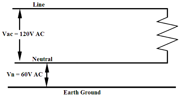
Figure 3: Example of a floating neutral. There is a 60V potential difference between earth ground and neutral (Vn).
Ground for Safety
The primary function of a ground is safety. Figure 4 shows a distribution system with a source and a load.
In the event that the insulation on the load should fail, the ground reference provides a low impedance path to earth.
This is because electrons are lazy by nature — they will always take the path of least resistance.
Proper grounding to earth ensures that a person is not the low impedance path. Grounding on electrical products is essential for ensuring safety within systems.
The dark side to grounding systems is that they can create issues that affect the rest of an electronic system.
Ideally, all ground systems would sit at the exact same earth ground reference.
This is not always the case and differences in ground potentials can cause safety hazards as well as issues with interference.
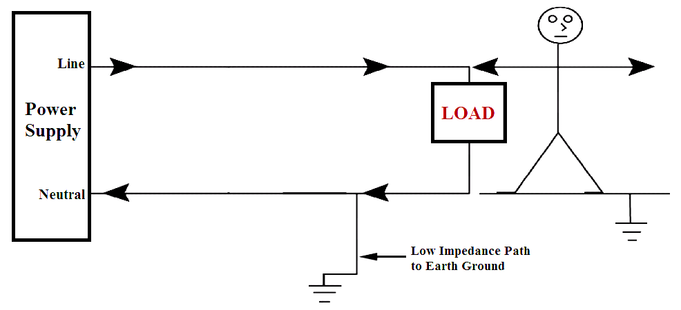
Figure 4: Distribution system with neutral tied directly to earth ground.
This provides a low impedance path to earth so in the event of a fault at the load, the person is not the path to ground.
Ground Noise
In a perfect world all points of a grounding system would be at the same potential.
In reality, it is not uncommon for different points of the same grounding system to sit at slightly different potentials.
This could be due to a number of reasons including the distance between grounding conductors and variations in soil resistance.
Large transients in voltage and current, sometimes due to lightning strikes can also cause issues with grounding networks. The end result is the existence small potential differences between grounding points.
A difference in potential, whether it is a few millivolts between PC data communication lines or hundreds of volts in transmission distribution networks, means that current can flow between those two points.
These variations in potential cause what are called “ground loops” throughout a system.
As shown in Figure 5, the difference in potential between the chassis ground on the power source and the chassis ground on the device under test has caused a ground loop.
The effects of ground loops depend on the severity of the potential difference between grounding points.
Small ground loops inject noise onto a system and cause interruption or loss of communication on data lines such as RS- 232 or other interfaces.
Large ground loops can damage electronic equipment and even pose safety hazards if the ground loop currents are large enough.
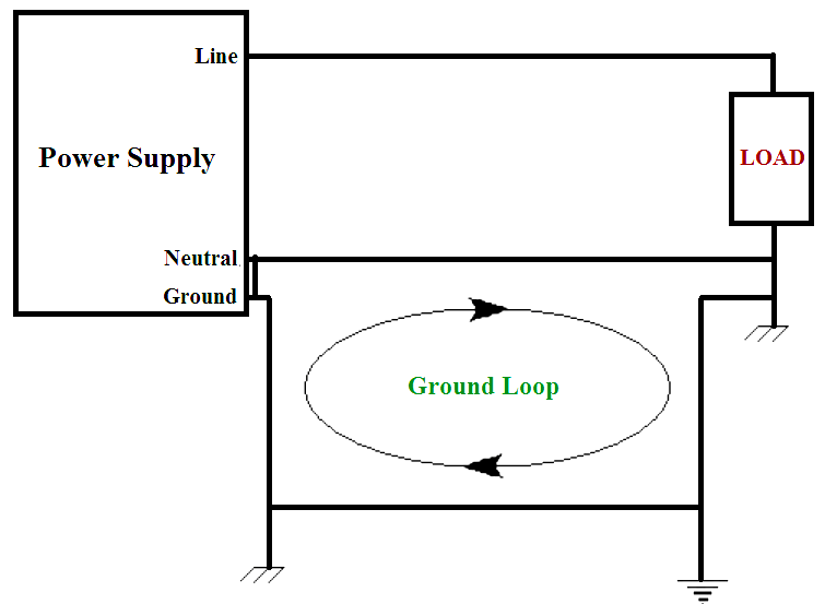
Figure 5: Ground loop due to difference in potential on chassis ground of source and chassis ground of load
It is possible to mitigate ground loops. Introducing multiple earth reference points, running equipment off of the same breaker panel (which shares a common ground) or separating mains voltage from communication lines are all methods used to reduce ground noise.
However, many facilities actually share grounding systems with other industrial complexes.
Large equipment in these facilities can introduce severe ground loops onto a ground system that are difficult to avoid.
In such cases it may be crucial to use a power source that can isolate sensitive equipment from the effects of ground loops.
Article Source: aptsources


nice piece of information.all the engineers shall take note and use for practical purposes
It Is also the most important one that i saw before
So ,if you have about refrigeration system pls sent to us
Thanks in advance
The diagram in figure 4 is very poor, it does not describe what’s said in the text and is dangerous. It looks like the person is touching the line voltage. Irrespective of a good earth connection, if a person touches for instance the a.c. mains line terminal, severe shock and perhaps death will result as their body provides an additional path to earth. Same if the line voltage is D.C. above 80 volts. The diagram needs changing !
A Floating Circuit could be quite nice in a clean laboratory environment, much like your new flashlight. Although in my world everything is cluttered with countess conductive mediums, each offering parallel fault current paths. Stray currents will inevitably develop between points along the power feed, points along the return feed, and between each. Currents will flow no matter what the resistance or number of faults greater than one.