Inst ToolsInst ToolsInst Tools
  • Courses
  • Automation
    • PLC
    • Control System
    • Safety System
    • Communication
    • Fire & Gas System
  • Instrumentation
    • Design
    • Pressure
    • Temperature
    • Flow
    • Level
    • Vibration
    • Analyzer
    • Control Valve
    • Switch
    • Calibration
    • Erection & Commissioning
  • Interview
    • Instrumentation
    • Electrical
    • Electronics
    • Practical
  • Q&A
    • Instrumentation
    • Control System
    • Electrical
    • Electronics
    • Analog Electronics
    • Digital Electronics
    • Power Electronics
    • Microprocessor
Search
  • Books
  • Software
  • Projects
  • Process
  • Tools
  • Basics
  • Formula
  • Power Plant
  • Root Cause Analysis
  • Electrical Basics
  • Animation
  • Standards
  • 4-20 mA Course
  • Siemens PLC Course
Reading: What is Flapper Nozzle System ?
Share
Notification Show More
Font ResizerAa
Inst ToolsInst Tools
Font ResizerAa
  • Courses
  • Design
  • PLC
  • Interview
  • Control System
Search
  • Courses
  • Automation
    • PLC
    • Control System
    • Safety System
    • Communication
    • Fire & Gas System
  • Instrumentation
    • Design
    • Pressure
    • Temperature
    • Flow
    • Level
    • Vibration
    • Analyzer
    • Control Valve
    • Switch
    • Calibration
    • Erection & Commissioning
  • Interview
    • Instrumentation
    • Electrical
    • Electronics
    • Practical
  • Q&A
    • Instrumentation
    • Control System
    • Electrical
    • Electronics
    • Analog Electronics
    • Digital Electronics
    • Power Electronics
    • Microprocessor
Follow US
All rights reserved. Reproduction in whole or in part without written permission is prohibited.
Inst Tools > Blog > Control Valves > What is Flapper Nozzle System ?

What is Flapper Nozzle System ?

Last updated: August 29, 2019 9:09 pm
Editorial Staff
Control Valves
No Comments
Share
2 Min Read
SHARE

A very important signal conversion is from pressure to mechanical motion and vice versa. This conversion can be provided by a flapper nozzle system (sometimes called as baffle/nozzle system).

 Flapper Nozzle System

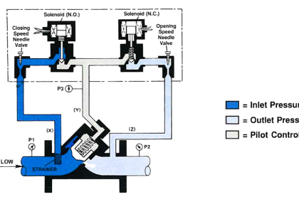
A diagram of this device is shown in Fig.I below.

Flapper nozzle system

A regulated supply of pressure, usually 20 psig, provides a source of air through the restriction. The nozzle is open at the end where the gap exists between the nozzle and flapper, and air escapes in this region.

If the flapper moves down and closes off the nozzle opening so that no air leaks, the signal pressure will rise to the supply pressure.

As the flapper moves away, the signal pressure will drop because of leaking of the leaking air. Finally, when the flapper is far away, the pressure will stabilize at some value determined by the maximum leak through the nozzle.

Flapper nozzle graph

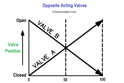
Fig II shows the relationship between signal pressure and gap distance. Note the great sensitivity in the central region. A nozzle/flapper is designed to operate in the central region where the slope of the line is greatest.

In this region, the response will be such that a very small motion of the flapper can change the pressure by an order of magnitude.

Note :

  • By adding a Electro-Magnet & supportive springs, we use this system as Current to Pressure Converter (I/P Converter).
  • By adding an LVDT assembly & supportive springs, we use this system as Pressure to Current Converter. (P/I Converter).

We will discuss in detail about I/P Converter and P/I Converter in separate topics, check below.

Also Read :

  1. Current to Pressure (I/P) Converter

  2. Pressure to Current (P/I) Converter

Reference : apexinnovations

Don't Miss Our Updates
Be the first to get exclusive content straight to your email.
We promise not to spam you. You can unsubscribe at any time.
Invalid email address
You've successfully subscribed !

Continue Reading

What is a 2-way Solenoid Valve ?
Solenoid Actuated Valves
Self-actuated Temperature Regulator – Principle, Types, Advantages
Thermostatic Valves Working Principle
What is Pump Cavitation? How to Avoid Cavitation?
What is Lift Check Valve ?
Share This Article
Facebook Whatsapp Whatsapp LinkedIn Copy Link
Share
Leave a Comment

Leave a Reply Cancel reply

Your email address will not be published. Required fields are marked *

Stay Connected

128.3kFollowersLike
69.1kFollowersFollow
208kSubscribersSubscribe
38kFollowersFollow

Categories

Explore More

Basics of Control Valve Sizing
Dampers and Louvres
How Gate Valves Work ?
Solenoid Valves Practical Problems
Basic Parts of Control Valves
SIS Final Control Elements
Valve Actuator Bench Set
How do you do control valve sizing in Layman’s terms?

Keep Learning

Control Valve End Connection

Control Valve End Connection

Valve Technician Interview Questions

Valve Technician Interview Questions

valve-actuator

Pneumatic Control Valve Actuators

Deluge Valve Operation using Solenoid Valve Animation

Deluge Valve Operation

Types of Control Valves Noise

Types of Control Valves Noise

Pressure Control Valve

What is Pressure Control Valve?

BALL CHECK VALVE THEORY

Types of Check Valves

What is Blowdown Valve (BDV)

What is Blowdown Valve (BDV)?

Learn More

Power Systems Questions & Answers

Power Systems MCQ Series 17

What is electrical transformer

Transformer Impedance Ratio

Types of Fuses

Electrical System Components and Protection Devices

Important Factors Consider during Piping Design

Important Factors Consider during Piping Design

Valve Basics

Basics of Control Valves

Butterfly Valve Failure caused Fire

Butterfly Valve Failure Caused Serious vicinity Heavy Fire

Baffle Nozzle Question

Baffle Nozzle Question

S7 Organizational blocks

Siemens PLC Tia Portal – OB100 Start-up Organization Block

Follow US
All rights reserved. Reproduction in whole or in part without written permission is prohibited.
Welcome Back!

Sign in to your account

Username or Email Address
Password

Lost your password?