Automatic Sprinklers
Automatic sprinklers are thermosensitive devices designed to react at predetermined temperatures by automatically releasing a stream of water and distributing it in specified patterns and quantities over designated areas.
Principle of Operation
- Under normal conditions, water discharged from an automatic sprinkler is restrained by a cap or valve.
- The cap/valve are held tightly against the orifice by a system of levers and links, or other releasing devices, pressing down on the cap and anchored firmly by struts on the sprinkler.
- Attached to the frame of the sprinkler is a deflector which direct and convert the stream of water into a spray designed to cool or protect a certain area.
- The amount of water discharged depends upon the flowing water pressure and the size of the sprinkler orifice.
- The speed of operation depends on the physical properties of the thermosensitive mechanism of the sprinkler.
- The time involved to operate depends, amongst other factors, upon the shape, size and mass of the thermosensitive mechanism, and the temperature differential between the surrounding atmosphere and the operating temperature of the sprinkler.
The two common types of operating elements are as follows:
1.Frangible type (e.g. Quartzoid bulb sprinkler)
The small bulb, usually of pyrex glass, contains a liquid which does not completely fill the bulb, leaving a small air bubble entrapped in it. As the liquid is expanded by heat, the bubble is compressed and finally absorbed by the liquid. As soon as the bubble disappears, the pressure rises infinitely and the bulb shatters, releasing the valve cap. The exact temperature is regulated by adjusting the amount of liquid and the size of the bubble when the bulb is sealed.
2.Fusible type (e.g. Soldered strut sprinkler)
It operates upon the fusing of a metal alloy of predetermined melting point.
So, Types of Automatic Sprinklers are as follows
The 2 basic type of automatic sprinkler are:
- Quartzoid bulb sprinkler
- Soldered strut sprinkler
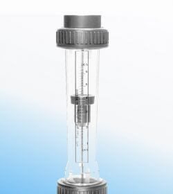
Quartzoid Bulb Detector
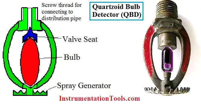
The above figure shows a quartzoid bulb detector or sprinkler (QBD). In this type the sprinkler incorporates a quartzoid bulb filled with a highly expansive coloured liquid having different expansion rates. Different QBD have different temperature ratings.
When a fire occurs in an adjacent area to this bulb the fluid expands until the air space is filled, increasing internal pressure causes the bulb to fracture. The size of the air gap determines the temperature at which this failure occurs. The valve plug falls out and a jet of water exits , striking the spray generator where it is then distributed evenly over the surrounding area. In acting this way only the area of the fire is deluged and damage is minimized
Apart from the QBD we have another sprinkler we use generally called soldered type sprinkler.
Soldered Strut Sprinkler
The below shows a soldered-strut sprinkler. It consists of three bronze plates joined together by special solder. These plates hold a valve in position against an orifice in a flexible diaphragm and seal the water outlet.
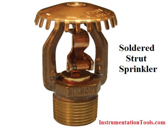
When the space is hot and the fusible solder melts, the plates fall apart, the valve drops and water flows to the deflector to cause a water spray over the fire.


thanks for the given information. its very usefull. if u dont mind pls give the information about PLC and ladder logic programing sir.
it is easy to understand and helpful for tracking the error by simple way.
thank you for good information.