How to do the Fire & Gas System Pre-Commissioning Activities, Fire Alarm System Commissioning procedure, Fire Alarm Control Panel Commissioning steps.
Contents
Fire Alarm System Commissioning

Fire Alarm System Pre-Commissioning Activities
- Check all panels, detectors and indicators are installed in their proper location.
- Ensure work access is permitted at all fire equipment installation locations on site.
- Ensure temporary mains supply for the programming computer is made available at each control panel location.
- Ensure installation technicians (preferably those involved in the system installation and cabling) are present on site with necessary tools.
- Check third party equipment technicians are available for interface testing.
- Ensure the backup batteries are fully charged.
Fire Alarm System Commissioning Activities
I) Testing Procedure
A) Continuity:
- Check the loop in and loop out continuity.
- Rectify by checking the device continuity for short circuit if the required continuity is not achieved.
- Terminate to the loop in and loop out points of the Fire Alarm Control Panel
B) Detector & Supervisory Devices
- Testing will precede one loop at a time.
- All initiating devices including manual pull stations will be individually operated and the indications at the fire panel, PC monitor are checked to ensure that the information is correct.
- Supervisory devices will be operated individually and checks made to ensure that the displayed information at the panel, PC monitor and printer is correct.
- Output devices to operate external equipment also to be checked.
II) Operation of Initiating Devices:
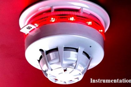
A) Smoke & Heat Detectors
- Check that the green indicator LED is pulsating
- Activate peripheral devices randomly using a chemical smoke aerosol, Heat gun (for Heat detectors)
- After activation check that the red indicator LED is steady.
- Check if the correct message is displayed on the panel display.
B) Double Action Addressable Pull Station
These will be activated randomly.Check if the correct message is displayed on the panel display.
III) Operation of Audible Notification Devices.
This test has two distinct purposes. To prove the correct messages are being received on the floors and that the audibility is correct.
- Initiate one floor for audible alarms at a time and visit the devices randomly to determine that they are all operational.
- Set Audio levels.
IV) Audible/Visual Notification Signals Operating Sequence
- Initiate a fire alarm signal by operating a Break Glass Unit.
- An evacuated signal will be activated on the alarmed floor of incidence and the floor above and the floor below.
- Reset the Break Glass Unit and reset the fire alarm panel by pressing Reset button.
- This test can be combined with the device testing.
- Leave the alarm system active for the first device test, check the audible signals and then silence the alarm system for the remainder of the device testing.
V) Fire Man Telephones Testing Sequence
- Plug in a telephone jack with a fireman telephone for communication.
- Check if the correct message is displayed on the panel.
- Check for the audible level is sufficient.
VI) Power Failure Test
The electrical power source for the fire alarm panel will be turned off and panel tests will be performed during battery powered stage.
VII) Fire Alarm Control Panel Commissioning
- Visually check for the LCD Display, LED status, microphone, wiring and batteries in the control panel.
- On the LCD display check for date & time, normal state display, alarm state display, trouble state display, panel buzzer, key functions and LED display.
- Battery to be sized for required backup and check the operation by disconnecting and connecting the batteries. Check for status indication and charger operation.
- Inspect the Fire phone display and check for the communication & multiple calls and response with off hook.
- Audio operations to be checked as audio in alarm condition, pre-recorded messages and check for the Fire phone paging and manual paging.
- Schedule operations, device response time, network operation, auxiliary outputs and alarm from other nodes to be checked.
VIII) Integration test and Interface with other services
- The interface with Lifts, Jet Fans, LPG, Elevators, HVAC Equipment, access Control etc. are achieved by activation of Control relay module in Alarm condition. Check if the correct message is displayed in sequence.
- The interface with Fire Fighting equipment, status monitoring of flow control and supervisory valves and Inert Gas System status monitoring is achieved by the dual input monitoring module. Check if the correct message is displayed in sequence.
- Sprinkler flow switches will be activated individually by opening the test valve at the zone control valve station and running water to drain.
- Check if the correct message is displayed on the panel display and PC monitor.
- BMS interfacing is achieved by software integration via BACnet. Upon integrating to the BMS panel check whether the communication is achieved and the required data is transferred.
Articles You May Like :
Rate of Rise Thermal Detectors


Articles are useful and helpful