These gauges are directly bonded (that is pasted) on the surface of the structure under study. Hence they are termed as bonded strain gauges.
The three types of bonded strain gauges are
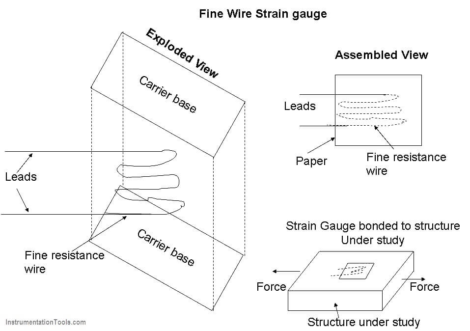
Fine Wire Strain Gauge
The arrangement consists of following parts,
A fine resistance wire diameter 0.025 mm which is bent again and again as shown in diagram. This is done to increase the length of the wire so that it permits a uniform distribution of stress. This resistance wire is placed between the two carrier bases (paper, Bakelite or Teflon) which are cemented to each other. The carrier base protects the gauge from damages. Leads are provided for electrically connecting the strain gauge to a measuring instrument (Wheatstone bridge).
Operation
With the help of an adhesive material, the strain gauge is pasted/bonded on the structure under study. Now the structure is subjected to a force (tensile or compresive). Due to the force, the structure will change the dimension. As the strain gauge is bonded to the structure, the stain gauge will also undergo change in both in length and cross-section (that is, it strained).
This strain (change in dimension) changes the resistance of the strain gauge which can be measured using a wheat stone bridge. This change in resistance of the strain gauge becomes a measure of the extent to which the structure is strained and a measure of the applied force when calibrated.
Fine Wire strain gauge Materials
Material Composition
- Nichrome Ni – 80% ; Cr – 20%
- Constantan Ni – 45%; Cu – 55%
- Nickel
- Platinum
- Isoelastic Ni – 36%; Cr – 8%; Mo – 0.5%
Advantages of Fine Wire Strain Gauge
- The range of this gauge is +/- 0.3% of strain.
- This gauge has a high accuracy.
- Has a linearity of +/- 1%.
Limitation of Fine Wire strain gauge
- These gauges cannot be detached and used again (because the gauges are bonded to the structure).
- These gauges are costly.