Inst ToolsInst ToolsInst Tools
  • Courses
  • Automation
    • PLC
    • Control System
    • Safety System
    • Communication
    • Fire & Gas System
  • Instrumentation
    • Design
    • Pressure
    • Temperature
    • Flow
    • Level
    • Vibration
    • Analyzer
    • Control Valve
    • Switch
    • Calibration
    • Erection & Commissioning
  • Interview
    • Instrumentation
    • Electrical
    • Electronics
    • Practical
  • Q&A
    • Instrumentation
    • Control System
    • Electrical
    • Electronics
    • Analog Electronics
    • Digital Electronics
    • Power Electronics
    • Microprocessor
  • Request
Search
  • Books
  • Software
  • Projects
  • Process
  • Tools
  • Basics
  • Formula
  • Power Plant
  • Root Cause Analysis
  • Electrical Basics
  • Animation
  • Standards
  • 4-20 mA Course
  • Siemens PLC Course
Reading: A Series of False Pressure Alarms
Share
Notification Show More
Font ResizerAa
Inst ToolsInst Tools
Font ResizerAa
  • Courses
  • Design
  • PLC
  • Interview
  • Control System
Search
  • Courses
  • Automation
    • PLC
    • Control System
    • Safety System
    • Communication
    • Fire & Gas System
  • Instrumentation
    • Design
    • Pressure
    • Temperature
    • Flow
    • Level
    • Vibration
    • Analyzer
    • Control Valve
    • Switch
    • Calibration
    • Erection & Commissioning
  • Interview
    • Instrumentation
    • Electrical
    • Electronics
    • Practical
  • Q&A
    • Instrumentation
    • Control System
    • Electrical
    • Electronics
    • Analog Electronics
    • Digital Electronics
    • Power Electronics
    • Microprocessor
  • Request
Follow US
All rights reserved. Reproduction in whole or in part without written permission is prohibited.
Inst Tools > Blog > Practical Questions > A Series of False Pressure Alarms

A Series of False Pressure Alarms

An operator reports a series of false pressure alarms reported by pressure indicating controller or recorder every few minutes.

Last updated: September 7, 2020 9:07 pm
Editorial Staff
Practical Questions
1 Comment
Share
2 Min Read
SHARE

An operator reports a series of false pressure alarms reported by pressure indicating recorder PIR-139 every few minutes.

An instrument technician investigated this problem the previous day and declared it was most likely due to an electrical wiring fault between PT-139 and PIR-139 after measuring some intermittent high-current signals at the input terminals of PIR-139:

A Series of False Pressure Alarms

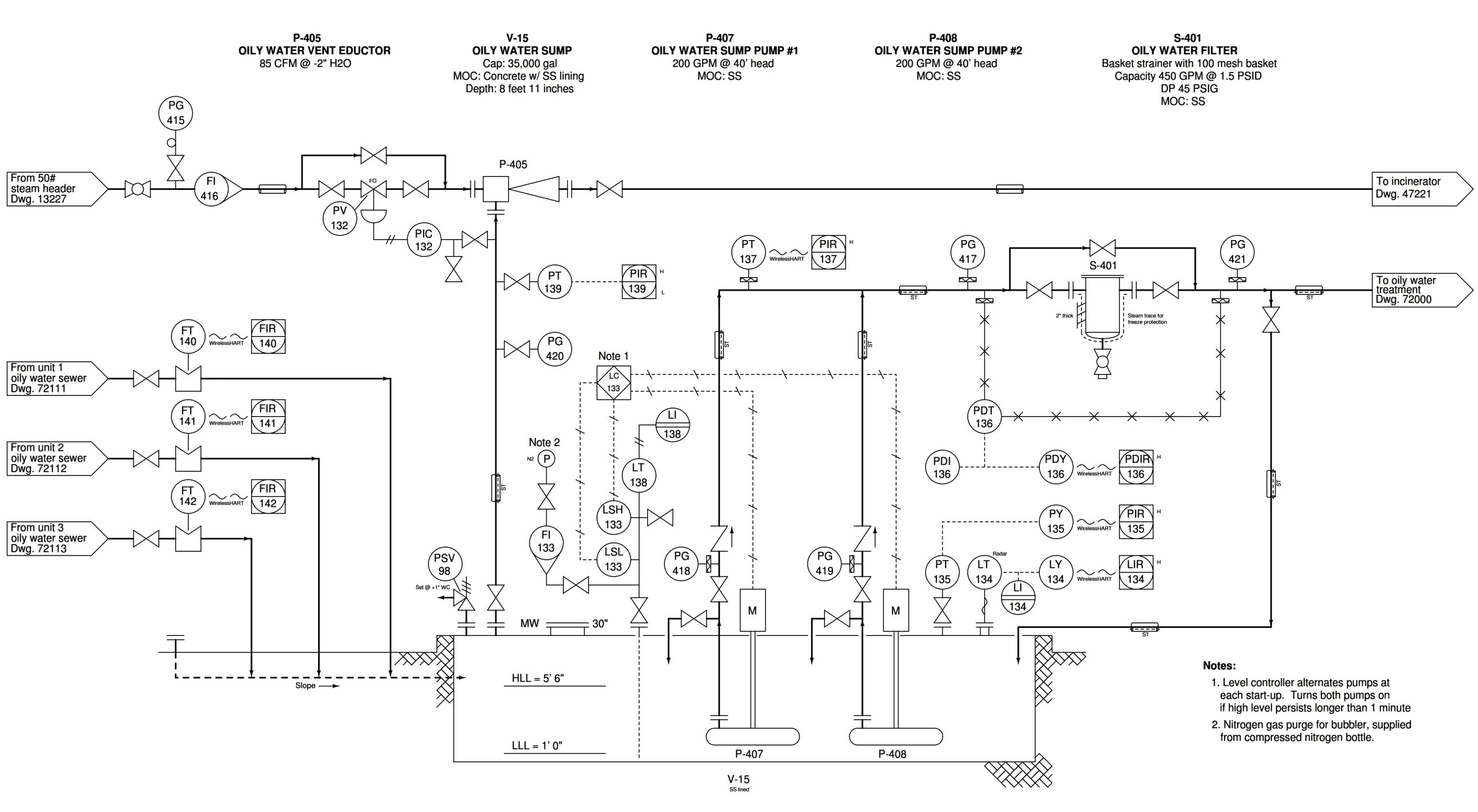
You are called to re-examine this system because the other instrument technician didn’t actually do anything to fix the problem. Your first test is to close the block (isolation) valve between PT-139 and the process pipe. After doing this, the mysterious pressure alarms cease. Later, you re-open that block valve, and the pressure alarms resume.

Explain what the results of this simple test tell you about the nature and location of the fault. Does it confirm the first technician’s diagnosis, or does it point to something else being wrong? Explain your answer in detail.

One detail not described in the scenario is just how the first technician measured those intermittent high-current signals at PIR-139. Presumably, it could have been done by continuously monitoring the display of a digital multimeter (DMM) long enough to see an alarm event occur. However, if the alarm events were infrequent enough, this could be a laborious task for someone to continuously watch a meter waiting to see the current change. Describe how you could use the Min/Max mode of a DMM instead to “automate” this task and free up the technician’s time.

Share your answers with us through the below comments section.

Read Next:

  • Instrument Technician Tools
  • Pressure Transmitter Re-Range
  • Identify Pressure Gauge Error
  • Pressure Control Problems
  • Instrument Technician Questions

Credits: Tony R. Kuphaldt

Don't Miss Our Updates
Be the first to get exclusive content straight to your email.
We promise not to spam you. You can unsubscribe at any time.
Invalid email address
You've successfully subscribed !

Continue Reading

Upgrading the Electrical System in an Automobile
Calculate the Transmitter Values
Calculate Differential Pressure Sensed by Level Transmitter
Overhead Product Pressure Control Loop
Displacer Level Transmitter 5-point Calibration
Calculate 0%, 50%, and 100% Calibration Points for ΔP transmitter
Share This Article
Facebook Whatsapp Whatsapp LinkedIn Copy Link
Share
1 Comment
  • Ben says:
    September 10, 2020 at 7:54 pm

    When I, the second instrument technician, shut the block valve to the transmitter as my first test and the pressure alarm stopped occurring, it was evidence to me that either the pressure sensor was faulty or that the alarms weren’t actually false.

    Reply

Leave a Reply Cancel reply

Your email address will not be published. Required fields are marked *

Stay Connected

128.3kFollowersLike
69.1kFollowersFollow
210kSubscribersSubscribe
38kFollowersFollow

Categories

Explore More

Identify the Pressure Gauge Error
DP Transmitter Problem
Calculate Density and Specific Gravity
Questions on Allen-Bradley MicroLogix 1000 PLC
Determine Level of Liquid in the Vessel and its Specific Gravity
Why Pressure Vessel Connected to Tubing System?
Differential Pressure Measurement across Baghouse
Pneumatic Level Transmitter Calibration Table

Keep Learning

Simple Pressure Transmitter Circuit

Pressure Transmitter using Potentiometer and Diaphragm

pressure switch control two lamps wiring

Draw Wiring of a Pressure Switch to control two lamps

Signal Strength of Guided-wave Radar Level Instrument

Signal Strength of Guided-wave Radar Level Instrument

PSV lift pressure

Calculate PSV Lift Pressure

Digital Pressure Gauge Animation

Air Pressure Inside the Tank

thermocouple Transmitter Formula

Calculate Process Temperature using a Thermocouple

Displacer Type Density Transmitter

Displacer Type Density Transmitter Question

Allen-Bradley MicroLogix 1000 controller

PLC Switch Actuation Status

Learn More

Electrical Machines Questions and Answers

Power Flow Through an Inductive Impedance Questions

PLC Modbus Communication

Introduction to Modbus – Reading and Writing Data

Connection between PLC and Contactor

Contactor – Basics, Wiring, Connection with PLC

PLC Program for Boolean Expression

PLC Program for Boolean Expression

Instrument Percent of Span Error

Instrument Percent of Span Error

Why have been limits imposed on the frequency ratio for thermowells?

Solenoid Valves Selection Guidelines

Solenoid Valves Selection Guidelines

Electrical Terminology

Electrical Terminology

Menu

  • About
  • Privacy Policy
  • Copyright

Quick Links

  • Learn PLC
  • Helping Hand
  • Part Time Job

YouTube Subscribe

Follow US
All rights reserved. Reproduction in whole or in part without written permission is prohibited.
Welcome Back!

Sign in to your account

Username or Email Address
Password

Lost your password?