Inst ToolsInst ToolsInst Tools
  • Courses
  • Automation
    • PLC
    • Control System
    • Safety System
    • Communication
    • Fire & Gas System
  • Instrumentation
    • Design
    • Pressure
    • Temperature
    • Flow
    • Level
    • Vibration
    • Analyzer
    • Control Valve
    • Switch
    • Calibration
    • Erection & Commissioning
  • Interview
    • Instrumentation
    • Electrical
    • Electronics
    • Practical
  • Q&A
    • Instrumentation
    • Control System
    • Electrical
    • Electronics
    • Analog Electronics
    • Digital Electronics
    • Power Electronics
    • Microprocessor
  • Request
Search
  • Books
  • Software
  • Projects
  • Process
  • Tools
  • Basics
  • Formula
  • Power Plant
  • Root Cause Analysis
  • Electrical Basics
  • Animation
  • Standards
  • 4-20 mA Course
  • Siemens PLC Course
Reading: Explain Operation of the Lamp Circuit ?
Share
Font ResizerAa
Inst ToolsInst Tools
Font ResizerAa
  • Courses
  • Design
  • PLC
  • Interview
  • Control System
Search
  • Courses
  • Automation
    • PLC
    • Control System
    • Safety System
    • Communication
    • Fire & Gas System
  • Instrumentation
    • Design
    • Pressure
    • Temperature
    • Flow
    • Level
    • Vibration
    • Analyzer
    • Control Valve
    • Switch
    • Calibration
    • Erection & Commissioning
  • Interview
    • Instrumentation
    • Electrical
    • Electronics
    • Practical
  • Q&A
    • Instrumentation
    • Control System
    • Electrical
    • Electronics
    • Analog Electronics
    • Digital Electronics
    • Power Electronics
    • Microprocessor
  • Request
Follow US
All rights reserved. Reproduction in whole or in part without written permission is prohibited.
Inst Tools > Blog > Practical Questions > Explain Operation of the Lamp Circuit ?

Explain Operation of the Lamp Circuit ?

Last updated: June 6, 2018 9:55 am
Editorial Staff
Practical Questions Instrumentation Design
No Comments
Share
1 Min Read
SHARE

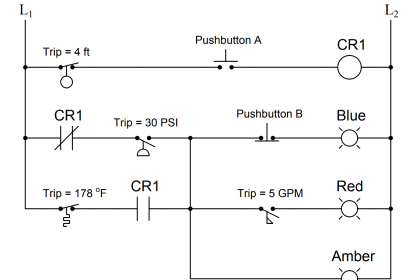
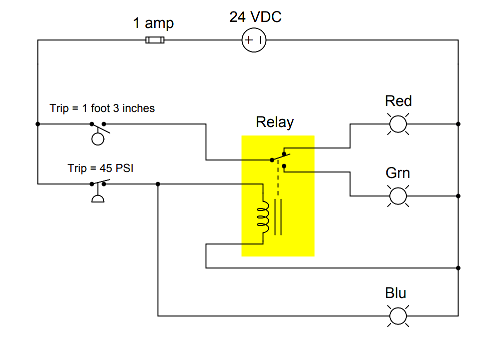
Explain the operation of the circuit ?

Explain operation of the circuit

Answer :

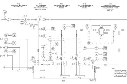
The blue lamp will be energized whenever the pressure switch senses a pressure that is less than 45 PSI.

The red and green lamps will both be de-energized whenever the level senses a level less than 1 foot 3 inches.

If that switch senses a level greater than 1 foot 3 inches, either the red lamp or the green lamp will energize (not both simultaneously!) based on the pressure switch’s state:

A pressure less than 45 PSI energizes the relay coil and energizes the green lamp, while a pressure greater than 45 PSI de-energizes the relay coil and energizes the red lamp.

Share Your Answer / Comments

Credits : by Tony R. Kuphaldt – under CC BY 1.0

Don't Miss Our Updates
Be the first to get exclusive content straight to your email.
We promise not to spam you. You can unsubscribe at any time.
Invalid email address
You've successfully subscribed !

Continue Reading

Switch or Transmitter
Relay Latching Circuit using Push Button
Top 10 Facts about HART Technology
Hydrostatic Pressure Measurement Questions
Important Factors Consider during Piping Design
What is SAMA Diagram?
Share This Article
Facebook Whatsapp Whatsapp LinkedIn Copy Link
Share
Leave a Comment

Leave a Reply Cancel reply

Your email address will not be published. Required fields are marked *

Stay Connected

128.3kFollowersLike
69.1kFollowersFollow
210kSubscribersSubscribe
38kFollowersFollow

Categories

Explore More

Practical Process Control System Questions & Answers – 8
All About Variable Area Flow Meters
Measure the Temperature of the RTD
Practical Process Control System Questions & Answers – 2
Testing of Pneumatic Systems
Programmable Logic Controller (PLC) Questions and Answers – 7
A Question on Steam Drum Water Level Measurement
How to Connect Proximity Switch (Source Type) to Make LED ON ?

Keep Learning

PLC program to control a water pump

PLC Program to Control a Water Pump

Connect the Differential Pressure Gauge at the Filter

How Do You Connect the Differential Pressure Gauge at the Filter?

DCS Vs PLC

Difference between DCS & PLC Systems

Signal Strength of Guided-wave Radar Level Instrument

Signal Strength of Guided-wave Radar Level Instrument

Pre-Engineering Design Documents

Industrial Automation Pre-Engineering Design Documents – Project & Process

Current-to-Pressure Transducer Calibration Table

hydraulic module

Identify all Spool Valve Positions

Impulse Line Problems

What are Impulse Lines? – Impulse Line Problems & Solutions

Learn More

types of Orifice Plates

Types of Orifice Plates & Orifice Plate Tappings

Transformer Coil Polarity

Transformer Coil Polarity

Advantages and Applications of zigzag transformer

What is a Tachometer

What is a Tachometer? – Types, Working Principle

O Ring Failure

How O-Ring Failure caused NASA’s shuttle to Blast ?

Seismic Transducers Objective Questions

Seismic Transducers Objective Questions

Benefits of IoT in the Manufacturing Industry

Benefits of IoT in the Manufacturing Industry

Difference Between Remote IO and Distributed IO Systems

Difference Between Remote I/O and Distributed I/O Systems

Menu

  • About
  • Privacy Policy
  • Copyright

Quick Links

  • Learn PLC
  • Helping Hand
  • Part Time Job

YouTube Subscribe

Follow US
All rights reserved. Reproduction in whole or in part without written permission is prohibited.
Welcome Back!

Sign in to your account

Username or Email Address
Password

Lost your password?