To read and interpret electrical system diagrams and schematics, one must be thoroughly familiar with the many symbols used. Once these symbols are mastered, most electrical diagrams and schematics will be understood with relative ease.
The symbols for the various electrical components that will appear on electrical diagrams and schematics are shown in Figure 30.
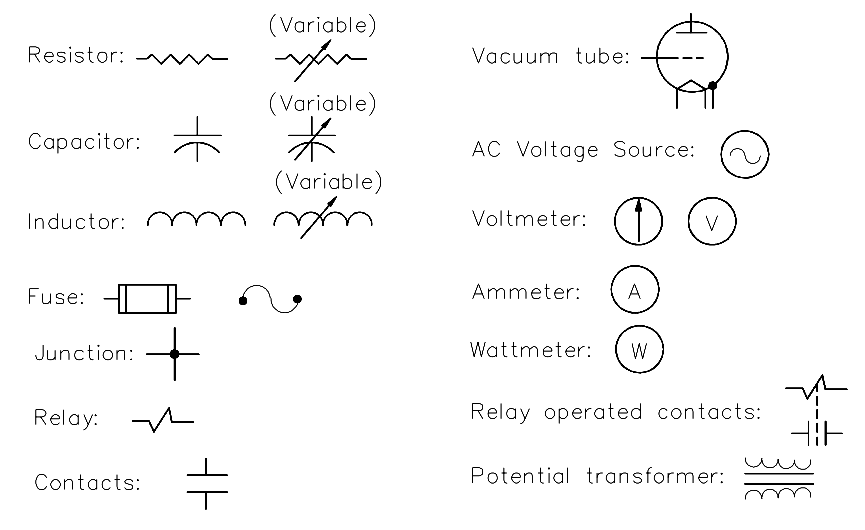
Figure 30 Electrical Symbols
Electrical Drives control the motion of electric motors. Motion control is required in industrial and…
PLC ladder logic design to control 3 motors with toggle switch and explain the program…
VFD simulator download: Master the online tool from the Yaskawa V1000 & programming software for…
The conveyor sorting machine is widely used in the packing industries using the PLC program…
Learn the example of flip-flop PLC program for lamps application using the ladder logic to…
In this article, you will learn the STAR DELTA programming using PLC controller to start…

